Eureka AIR delivers breakthrough ideas for toughest innovation challenges, trusted by R&D personnel around the world.

Sewage treatment equipment with deodorization function

A technology for sewage treatment equipment and deodorization function, which is applied in water/sewage treatment equipment, water/sewage treatment, water/sewage multi-stage treatment, etc. and other problems, to prevent the overflow of odor and improve its own functionality.

Inactive Publication Date: 2020-10-16
安徽恒宇环保设备制造股份有限公司
View PDF6 Cites 0 Cited by
  • Summary
  • Abstract
  • Description
  • Claims
  • Application Information

AI Technical Summary

Problems solved by technology

[0005] In order to overcome the traditional sewage treatment equipment in order to facilitate cleaning, open structure design is often adopted, so that after a long time of use of sewage treatment equipment, it is convenient for users to clean the interior of sewage treatment equipment, and its open structure design cannot handle sewage treatment Isolate the pungent smell emitted from time to time, so that the sewage treatment equipment will make the surrounding air filled with pungent smell during the sewage treatment process. It does not have a sewage deodorization structure and has a single function; secondly, the traditional sewage treatment equipment adopts manual cleaning. The internal cleaning operation increases the user's operation steps and reduces its cleaning efficiency; at the same time, the traditional sewage treatment equipment does not have an auxiliary filtering structure, so that impurities during sewage treatment are directly placed in the sewage treatment equipment, which is likely to cause equipment blockage , reduce its stability, and provide a kind of sewage treatment equipment with anti-odor function

Method used


Image

  • Sewage treatment equipment with deodorization function
  • Sewage treatment equipment with deodorization function
  • Sewage treatment equipment with deodorization function

Examples


Embodiment Construction

[0033] The technical solutions in the embodiments of the present invention will be clearly and completely described below in conjunction with the embodiments of the present invention. Apparently, the described embodiments are only some of the embodiments of the present invention, not all of them. Based on the embodiments of the present invention, all other embodiments obtained by persons of ordinary skill in the art without creative efforts fall within the protection scope of the present invention.

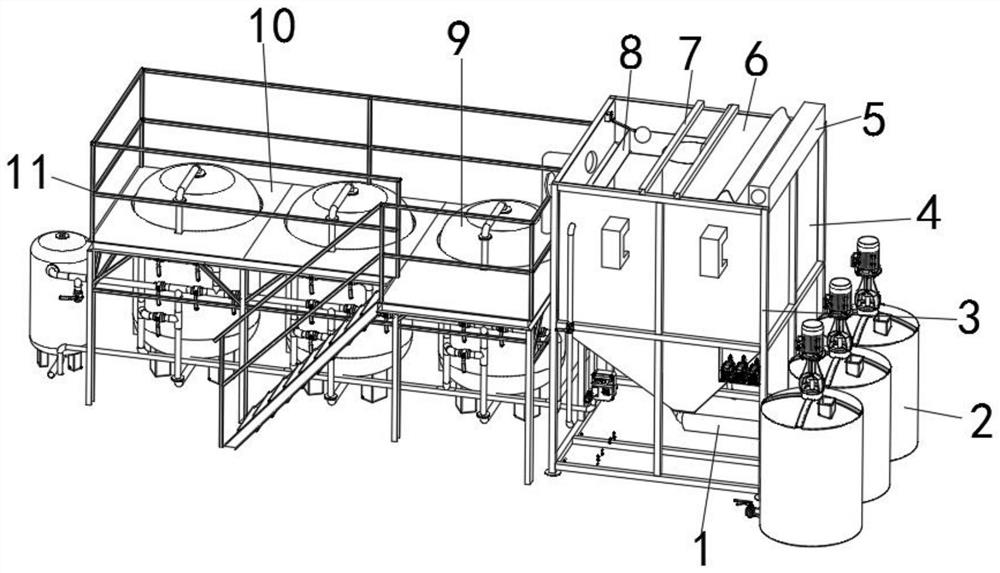
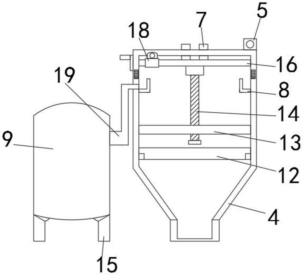
[0034] Such as Figure 1-6 As shown, a kind of sewage treatment equipment with anti-odor function comprises a fixed deck 10, a clean water tank 4 and a sewage tank 9, the clean water tank 4 is fixedly installed on one side of the fixed deck 10, and the sewage tank 9 is fixedly installed on a fixed Inside the deck 10, a first screw rod 14 is movably installed in the inner middle position of the clean water tank 4, and a splicing card frame 12 is fixedly installed on the inner side ...


PUM


Abstract

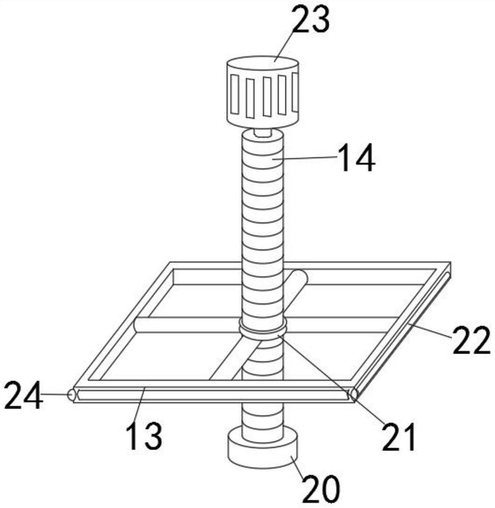
The invention discloses sewage treatment equipment with a deodorization function. The sewage treatment equipment comprises a fixed clamping seat, a purified water tank and a sewage barrel, the purified water tank is fixedly mounted on one side of the fixed clamping seat; the sewage barrel is fixedly mounted in the fixed clamping seat; a first screw rod is movably mounted in the middle of the innerside of the purified water tank; a splicing clamping frame is fixedly mounted on the inner side, close to the bottom end of the first screw rod, of the purified water tank; a lifting frame is movablyinstalled on the side edge of the first screw rod, a lifting screw ring is fixedly installed in the middle of the inner side of the lifting frame, the first screw rod and the lifting frame are movably connected through the lifting screw ring, a motor is arranged at the top end of the first screw rod, and a positioning chuck is fixedly installed on the outer surface of the bottom end of the firstscrew rod. The sewage treatment equipment is provided with an isolation deodorization structure, odor overflowing is avoided, meanwhile, the sewage treatment equipment is provided with a lifting cleaning structure, the using effect of the sewage treatment equipment is improved, and maintenance operation is more convenient.

Description

technical field [0001] The invention belongs to the technical field of sewage treatment equipment, in particular to a sewage treatment equipment with deodorizing function. Background technique [0002] Sewage treatment equipment is an industrial equipment that can effectively treat domestic sewage and industrial wastewater in urban areas. It prevents sewage and pollutants from flowing directly into waters, which is of great significance for improving the ecological environment, improving urban quality and promoting economic development. [0003] The comparative document CN208700672U discloses a kind of sewage treatment equipment, which includes a container and a sedimentation tank unit. The container is constructed as a sewage treatment tank; the sedimentation tank unit is arranged in the sewage treatment tank, and the sedimentation tank unit includes a tank body and a mud bucket arranged under the tank body, and there is a gap between the tank body and the side plate of the...

Claims


Application Information

Patent Timeline
Patent Type & Authority Applications(China)
IPC IPC(8): C02F9/02
CPCC02F1/001C02F1/44C02F2201/004C02F2301/08C02F2303/02C02F2303/14
Inventor 王标王雨潞范晓雅
Owner 安徽恒宇环保设备制造股份有限公司
Why Eureka
Eureka Blog
Learn More