Electric transmission lock

A transmission locker and electric technology, which is applied in non-mechanical transmission-operated locks, building locks, door/window accessories, etc. It can solve the problem of large motors, windows with narrow frames that cannot be used, and windows that cannot be opened and turned inside. And other issues

Pending Publication Date: 2020-10-16
佛山市南悦精密机电有限公司
View PDF0 Cites 0 Cited by
  • Summary
  • Abstract
  • Description
  • Claims
  • Application Information

AI Technical Summary

Problems solved by technology

As a part of the intelligent window opening execution system, the electric transmission locker cannot be applied to the casement window and the motor volume is too large, whi

Method used


Image

  • Electric transmission lock
  • Electric transmission lock
  • Electric transmission lock

Examples


Embodiment 1

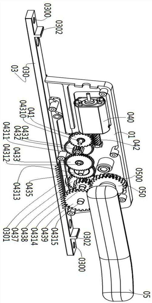
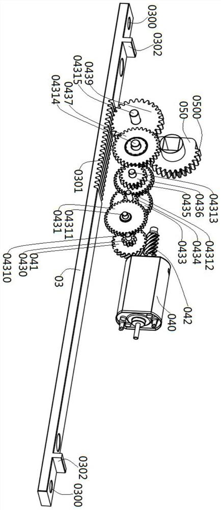
[0038] See attached Figure 1-5 It is a schematic diagram of the overall and partial structure of an embodiment of the present invention. The present invention specifically discloses an electric transmission lock, including: a casing 01, which is a hollow isosceles trapezoid with an open bottom; a base 02. The base 02 is a rectangular tank with openings at both ends. The shape and specification of the bottom surface of the casing 01 is the same as that of the top surface of the base 02 and is fixed with the top surface of the base 02 by bolts. Both the casing 01 and the base 02 are waterproof Design, the connection between the two and the respective openings are filled with sealant or waterproof gasket; the actuator 03, the actuator 03 passes through both ends of the base 02 and is installed in the space defined by the casing 01 and the base 02 and Can slide along the groove length direction of the base 02; the transmission mechanism 04, the transmission mechanism 04 includes ...

Embodiment 2

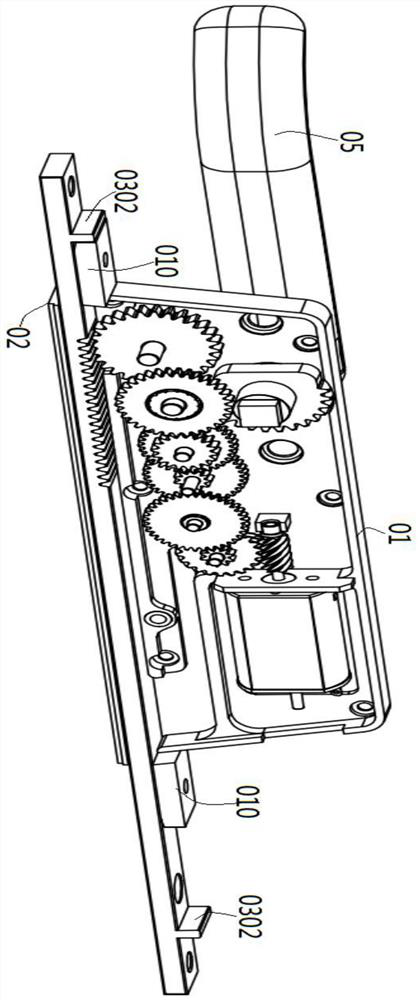
[0050] See attached Figure 6-9 It is a schematic diagram of the overall and partial structure of an embodiment of the present invention. The present invention specifically discloses an electric transmission lock, including: a casing 01, which is a hollow isosceles trapezoid with an open bottom; a base 02. The base 02 is a rectangular tank with openings at both ends. The shape and specification of the bottom surface of the casing 01 is the same as that of the top surface of the base 02 and is fixed with the top surface of the base 02 by bolts. Both the casing 01 and the base 02 are waterproof Design, the connection between the two and the respective openings are filled with sealant or waterproof gasket; the actuator 03, the actuator 03 passes through both ends of the base 02 and is installed in the space defined by the casing 01 and the base 02 and Can slide along the groove length direction of the base 02; the transmission mechanism 04, the transmission mechanism 04 includes ...


PUM


Abstract

The invention discloses an electric transmission lock which comprises a machine shell, a base, an executing mechanism, a transmission mechanism and a handle, wherein a rectangular trough body with openings at two ends serves as the base; the bottom surface of the machine shell is fixed with the top surface of the base; the executing mechanism penetrates through two ends of the base, is mounted ina space defined by the machine shell and the base, and can slide in the trough length direction of the base; the transmission mechanism comprises a motor, a worm gear, a worm and a speed-reducing gearset; after passing through the worm, the worm gear matched with the worm, and the speed-reducing gear set in sequence, an output shaft of the motor is in transmission connection with the executing mechanism; and the connecting end of the handle is in transmission connection with the speed-reducing gear set. The motor is adopted for bringing the worm gear, the worm and the speed-reducing gear setto drive the executing mechanism and the handle, so that the overall size of the electric transmission lock can be greatly reduced and the electric transmission lock can adapt to window frames of different thicknesses; and the electric transmission lock can be applied to not only flat-opening windows but also flat-opening inward tilt-turn windows, and thus the diversified requirements of users canbe met.

Description

technical field [0001] The invention relates to the field of intelligent doors and windows, and more specifically relates to an electric transmission locker. Background technique [0002] With the development of science and technology and the popularization of intelligence, smart window opening has been widely accepted by the public, and has entered thousands of households. As a part of the intelligent window opening execution system, the electric transmission locker cannot be applied to the casement window and the motor volume is too large, which has relatively strong restrictions on the width of the window aluminum profile window. Electric drive locks currently on the market cannot be used on narrow frame windows. [0003] Therefore, how to provide an electric transmission lock that can overcome the above-mentioned problems. It is a problem that those skilled in the art need to solve urgently. Contents of the invention [0004] In view of this, the present invention p...

Claims


Application Information

Patent Timeline
IPC IPC(8): E05B47/00E05B15/00E05B63/14E05B1/00E05B15/10
CPCE05B47/0012E05B47/0001E05B15/00E05B1/003E05B63/146E05B15/10E05B2047/002
Inventor 何赛华骆文源吴小英孙应龙
Owner 佛山市南悦精密机电有限公司
Why Eureka
Try Eureka