Air conditioning system and control method thereof

An air-conditioning system and control method technology, applied in the direction of air-conditioning systems, refrigerators, heating methods, etc., can solve the problems of low system energy efficiency, reduced comfort, low air-conditioning air temperature and indoor temperature, etc., to improve system energy efficiency and reduce Entrance specific enthalpy, effect of improving heating capacity

Pending Publication Date: 2020-10-16
GREE ELECTRIC APPLIANCES INC
View PDF1 Cites 16 Cited by
  • Summary
  • Abstract
  • Description
  • Claims
  • Application Information

AI Technical Summary

Problems solved by technology

[0006] Therefore, the technical problem to be solved by the present invention is to overcome the disadvantages of comfort reduction and low energy efficiency of the system caused by the air-conditioning air outlet temperature and indoor temperature being too low during dehumidification operation of the air-conditioning system in the prior art, thereby providing an air-conditioning system and its control method

Method used


Image

  • Air conditioning system and control method thereof
  • Air conditioning system and control method thereof
  • Air conditioning system and control method thereof

Examples


Embodiment Construction

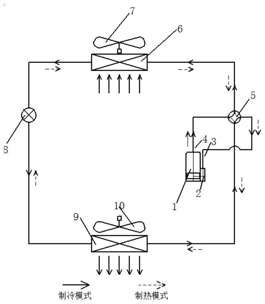
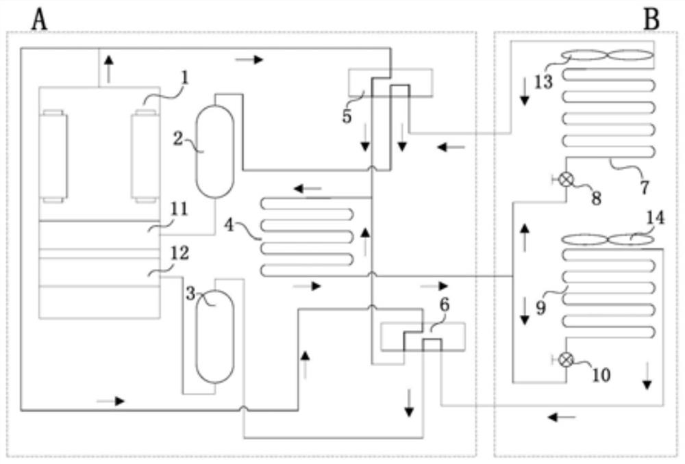
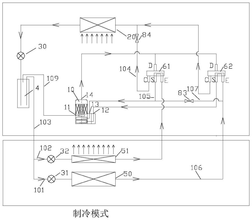
[0071] Such as Figure 3-26 As shown, the present invention provides an air conditioning system, which includes:

[0072] The compressor 10, the first indoor heat exchanger 50 and the second indoor heat exchanger 51;

[0073] It also includes a valve group structure, through which the switching control of the valve group structure can make: in the cooling mode, the first indoor heat exchanger 50 communicates with the suction port of the compressor 10, and the second indoor heat exchanger 51 connected to the suction port of the compressor 10; in the heating mode, the indoor first heat exchanger 50 is connected to the exhaust port of the compressor 10, and the indoor second heat exchanger 51 is connected to the The exhaust port of the compressor 10; in the reheating and dehumidifying mode, the first indoor heat exchanger 50 is connected to the suction port of the compressor 10, and the second indoor heat exchanger 51 is connected to the compressor the exhaust port of machine 1...


PUM


Abstract

The invention provides an air conditioning system and a control method thereof. The air conditioning system comprises a compressor, a first indoor heat exchanger and a second indoor heat exchanger; the air conditioner further comprises a valve set structure, and through switching control of the valve set structure, in the refrigeration mode, the indoor first heat exchanger communicates with an airsuction port of the compressor, and the indoor second heat exchanger communicates with the air suction port of the compressor; in the heating mode, the indoor first heat exchanger communicates with an exhaust port of the compressor, and the indoor second heat exchanger communicates with the exhaust port of the compressor; in the reheating dehumidification mode, the indoor first heat exchanger communicates with the air suction port of the compressor, and the indoor second heat exchanger communicates with the exhaust port of the compressor; and air flow can sequentially flow through the indoorfirst heat exchanger and the indoor second heat exchanger to complete heat exchange. According to the air conditioning system, the leeward side heat exchanger can be converted into the reheating heatexchanger under the control of the valve when the air conditioning system operates in the dehumidification mode in the transition season, so that the air supply temperature when the air conditioning system operates in the dehumidification mode is increased, the condensation temperature is reduced, the supercooling degree of the outlet of a condenser is increased, and the system energy efficiency is improved.

Description

technical field [0001] The invention relates to the technical field of air conditioning, in particular to an air conditioning system and a control method thereof. Background technique [0002] Existing as attached figure 1 When the conventional refrigeration and air-conditioning system shown is running in summer cooling or dehumidification in transitional seasons, in order to meet the dehumidification demand, it is usually necessary to lower the temperature of the evaporator to be lower than the dew point temperature of the return air, and the temperature difference between the two is large. [0003] When the conventional air-conditioning system is dehumidified during the rainy season in the middle and lower reaches of the Yangtze River in China or during the "return to the south" in southern China, the temperature of the air outlet and the indoor temperature will be too low, which will cause the human body to feel uncomfortable. [0004] In addition, the lower the evaporat...

Claims


Application Information

Patent Timeline
Patent Type & Authority Applications(China)
IPC IPC(8): F24F1/0063F24F11/65F25B13/00F25B41/00F25B41/04F25B43/00
CPCF25B13/00F25B41/00F25B43/00F24F11/65F24F1/0063
Inventor 梁祥飞皇甫启捷郑波黄明月
Owner GREE ELECTRIC APPLIANCES INC
Why Eureka
Try Eureka