Vortex type radiator

A radiator and vortex technology, applied in the field of vortex radiators, can solve the problems of low heat dissipation efficiency of radiators, achieve high utilization efficiency, speed up heat dissipation efficiency, and high space utilization

Pending Publication Date: 2020-10-16
安徽开华散热器制造科技有限公司
View PDF3 Cites 0 Cited by
  • Summary
  • Abstract
  • Description
  • Claims
  • Application Information

AI Technical Summary

Problems solved by technology

[0006] The technical problem to be solved by the present invention is: how to solve the problem of low cooling efficiency of the radiator

Method used


Image

  • Vortex type radiator
  • Vortex type radiator
  • Vortex type radiator

Examples


Embodiment 1

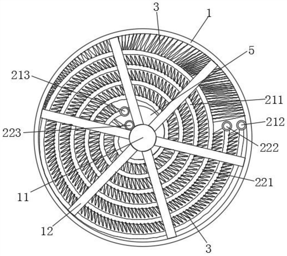
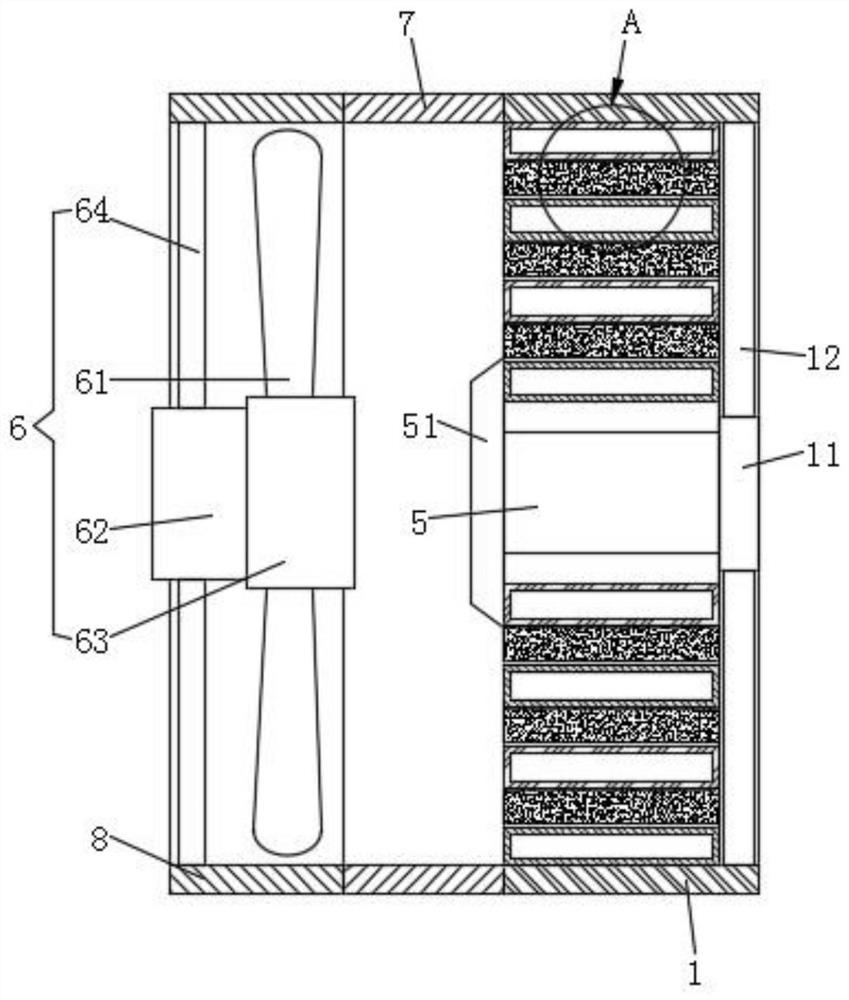
[0035] refer to image 3 , this embodiment discloses a scroll radiator, including a heat dissipation channel 7 . Along the front and rear sides of the central axis of the heat dissipation passage 7, the coaxial heat sink housing 1 and the heat dissipation fan housing 8 are sequentially connected by bolts. The heat dissipation channel 7, the heat sink shell 1 and the heat dissipation fan shell 8 are circular shells with equal diameters. The cooling fan 6 with the wind direction facing the cooling fin housing 1 is installed in the cooling fan housing 8 . combined reference figure 1 , the channel center of the heat sink shell 1 is provided with a fixed plate 11 , and the fixed plate 11 is fixed to the inner wall of the heat sink shell 1 through a connecting rod 12 . One end of the fixing plate 11 facing the cooling fan 6 is fixed with a connecting column 5 whose horizontal centerline is parallel to the centerline of the cooling fan 6 through bolts.

[0036] refer to figure 1...

Embodiment 2

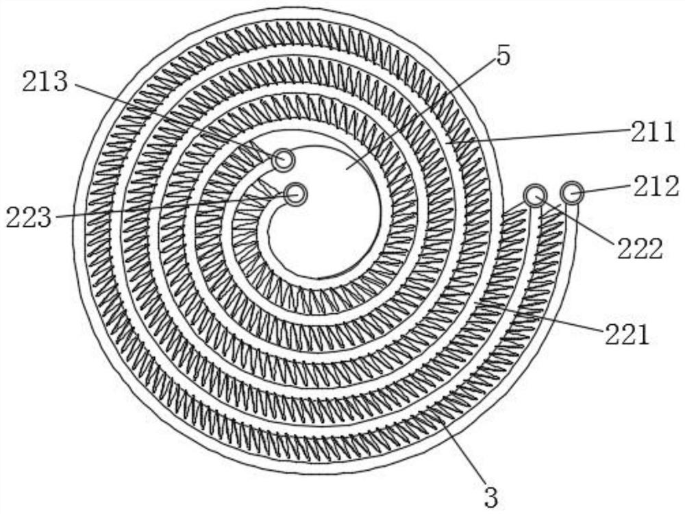
[0047] refer to Figure 5 The difference between the second embodiment and the first embodiment is that the outer circle of the connecting column 5 is only wound with a spiral third channel 231 once. A cooling fin 3 with the same vortex pitch, vortex direction and curvature as the vortex gap is embedded in the vortex gap of the third channel 231 . A third outlet 233 is defined at an inner end of the third channel 231 . A third inlet 232 is defined at the outer end of the third channel 231 .

[0048] Compared with Embodiment 1, in this embodiment, the outer circumference of the connecting column 5 is wound with a third passage 231. When there is only one cooling object, the structure of Embodiment 2 is used to make the cooling object in the third passage 231 In the case of being completely covered by the wind direction of the fan, the material consumption of the vortex radiator is greatly reduced.


PUM


Abstract

The invention discloses a vortex type radiator. The vortex type radiator comprises a heat dissipation channel. A heat dissipation fin shell and a heat dissipation fan shell which are coaxial are sequentially connected to the front side and the rear side of the central axis of the heat dissipation channel. The heat dissipation channel, the heat dissipation fin shell and the heat dissipation fan shell are circular shells with the same diameter. A heat dissipation fan with the wind direction facing the heat dissipation fin shell is installed in the heat dissipation fan shell. A fixing disc is arranged at the center of a channel of the heat dissipation fin shell and fixed to the inner wall of the heat dissipation fin shell through a connecting rod. A transverse connecting column is fixed to the end, facing the heat dissipation fan, of the fixing disc. A plurality of sets of channel assemblies are wound on an outer ring of the connecting column, and the vortex lines of the channel assemblies spread and amplify outwards by taking the central axis of the connecting column as a circle center. The channel walls of the channel assemblies are embedded in one another in sequence, and the distances between the adjacent channel walls are equal. The gaps between the adjacent inner walls of the multiple sets of channel assemblies and the gaps between the channel assemblies and the heat dissipation fin shell are filled with heat dissipation fins. The radiator is high in heat dissipation and air utilization efficiency and good in heat dissipation effect.

Description

technical field [0001] The invention relates to the technical field of radiator heat dissipation, in particular to a scroll radiator. Background technique [0002] The existing heat sink group is square as a whole, and the heat dissipation channel and the heat sink are arranged at intervals. The fluid or gas to be cooled passes through the heat dissipation channel, and the heat is exported to the heat sink, and then combined with the fan, blowing against the heat sink to blow The heat is exported quickly, but because the air outlet channel of the cooling fan is a circular channel, it is difficult to blow to the four corners of the square heat sink, and the fluid channels are easy to accumulate at the corners, and the speed is slow, which makes the heat dissipation of the square heat sink Efficiency is reduced, and the volume of the square cooling fins in the prior art combined with the fan is relatively large. [0003] Reference document 1 with publication number CN10870945...

Claims


Application Information

Patent Timeline
Patent Type & Authority Applications(China)
IPC IPC(8): F28D1/03F28F9/00F28F9/22F28F13/06
CPCF28D1/03F28F9/001F28F9/22F28F13/06
Inventor 包亮
Owner 安徽开华散热器制造科技有限公司
Why Eureka
Try Eureka