Energy monitoring system

A monitoring system and energy technology, applied in general control systems, control/regulation systems, instruments, etc., can solve the problems of many energy consumption data listing items, inaccurate positioning, long statistical period, etc., to ensure efficiency, display intuitive, Avoid wasteful effects

Active Publication Date: 2020-10-16
NAT INST OF METROLOGY CHINA
View PDF19 Cites 2 Cited by
  • Summary
  • Abstract
  • Description
  • Claims
  • Application Information

AI Technical Summary

Problems solved by technology

[0004] However, the energy monitoring devices in the prior art form energy consumption reports and energy consumption curves by comparing the statistical data with the original recorded data. There will be processing delays in the monitoring process, and it is impossible to solve the problems in the energy monitoring process in a timely manner
Especially in the existing technology, the energy consumption data is mostly used with the system, and the statistics are divided into items first, and then summarized to the management platform, resulting in waste of resources, repeated construction, and complicated summary.
In addition, the energy monitoring device in the prior art, on the one hand, needs to collect data through each device to form a report; on the other hand, it must cooperate with manual inspection to complete the monitoring of each energy-consuming equipment
Manual inspection consumes a lot of labor costs and time costs
The ability to solve emergencies is poor and cannot be accurately positioned, which will easily cause greater energy waste

Method used


Image

  • Energy monitoring system
  • Energy monitoring system
  • Energy monitoring system

Examples


Embodiment 1

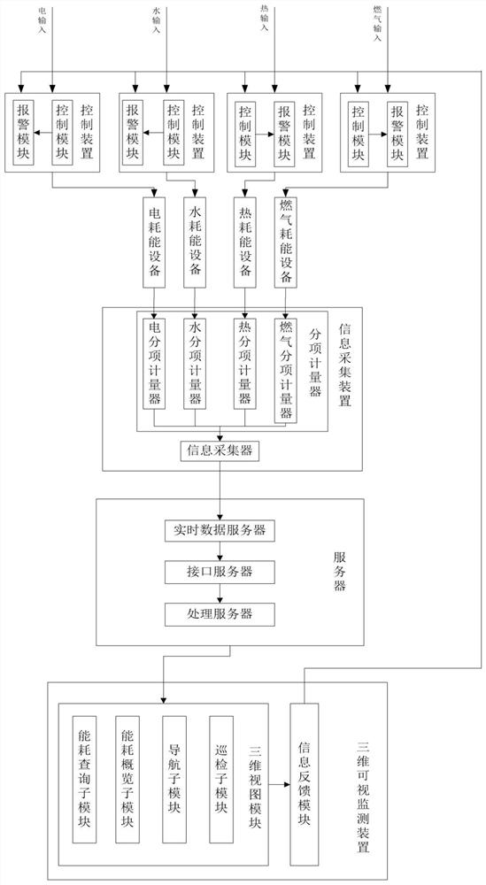
[0067] Such as figure 1 As shown, the present invention discloses an energy monitoring system, including: an information collection device, a server, and a three-dimensional visual monitoring device, the information collection device is electrically connected to the input end of the server, and the three-dimensional visual monitoring device is connected to the The above information collection device is electrically connected; wherein,

[0068] The information collection device is used to collect energy consumption data item by item, and transmit the energy consumption data to a server;

[0069] The present invention separately collects the consumption data of electricity, water, heat and gas through sub-item collection. The sub-item collection uses a plurality of sub-item meters to be electrically connected with energy-consuming equipment, and can respectively collect electricity energy-consuming equipment, water energy-consuming equipment, Gas energy-consuming equipment and ...

Embodiment 2

[0074] As an embodiment of the present invention: the information collection device includes sub-item meters, information collectors and energy consumption equipment; wherein,

[0075] The sub-item meter is electrically connected to the energy-consuming equipment, and the output end of the information collector is electrically connected to the input end of the sub-item meter; wherein,

[0076] The sub-item meters include: electricity sub-item meters, moisture sub-meters, heat sub-item meters, and gas sub-item meters.

[0077] In the present invention: the sub-item meters include electric sub-item meters, moisture sub-meters, heat sub-item meters, and gas sub-item meters. The itemized meters used in the present invention are not limited to the several itemized meters described in this embodiment. According to the actual application requirements, the energy types can be divided according to different requirements, and the data generated by the corresponding energy consumption c...

Embodiment 3

[0079] As an embodiment of the present invention: the sub-item meter and the information collector are linked through a twisted-pair shielded cable, and communicate with Modbus protocol for data transmission; wherein,

[0080] When the information collector receives the data transmission request of the sub-item meter, determine the device information of the sub-item meter, and when the device information is stored in the information collector, through the Modbus protocol The communication returns a response action; where,

[0081] The device information includes: device address, device category and device license code;

[0082] The information collector and the real-time data server are linked by a twisted-pair shielded cable, and communicate with the TCP / IP protocol for data transmission; wherein,

[0083] The TCP / IP protocol is used for detection and confirmation of the communication link between the sub-item meter and the information collector.

[0084] The principle of t...


PUM


Abstract

The invention provides an energy monitoring system. The energy monitoring system comprises an information acquisition device, a server and a three-dimensional visual monitoring device, wherein the information acquisition device is used for acquiring energy consumption data according to items and transmitting the energy consumption data to the server; the server is used for carrying out statisticalanalysis on the energy consumption data, determining an analysis result, converting the energy consumption data into three-dimensional energy consumption data and converting the analysis result intoa three-dimensional analysis result; and the three-dimensional visual monitoring device is connected with the server and is used for acquiring and displaying the three-dimensional energy consumption data and the three-dimensional analysis result. The beneficial effects of the invention are that: the service condition data of each energy source collected in a subentry manner is directly transmittedto the server, the process of collection by a plurality of systems and combination statistics is not needed, thereby achieving the effective utilization of resources, and solving the problems of complex summarization and repeated construction.

Description

technical field [0001] The invention relates to the technical field of energy management, in particular to an energy monitoring system. Background technique [0002] In the whole process of social development, due to the lack of human understanding of nature, the unrestrained use of energy resources in the process of seeking social development has resulted in the occurrence of energy exhaustion and non-renewable phenomena, and the problem of energy consumption has become increasingly prominent. In recent years, due to the worldwide energy shortage, the price of energy has been rising day by day. In order to alleviate the problem of energy consumption, various energy-saving renovation projects have emerged in an endless stream. The relevant national departments will implement the energy conservation and emission reduction indicators to the regions, and the provincial, municipal and regional governments will undertake the corresponding energy conservation tasks. The governmen...

Claims


Application Information

Patent Timeline
Patent Type & Authority Applications(China)
IPC IPC(8): G05B19/048
CPCG05B19/048
Inventor 吴渊张仕杰夏文卷高云峰胡松
Owner NAT INST OF METROLOGY CHINA
Why Eureka
Try Eureka