Defect detection method and device, electronic equipment and readable storage medium

A defect detection and defect technology, applied in the field of image processing, can solve problems such as strong subjectivity, low efficiency, and high cost

Pending Publication Date: 2020-10-16
创新奇智(上海)科技有限公司
View PDF0 Cites 2 Cited by
  • Summary
  • Abstract
  • Description
  • Claims
  • Application Information

AI Technical Summary

Problems solved by technology

[0003] For the objects on these non-planar printed matter, if the traditional manual detection method is used to realize, there are disadvantages such as high cost, low efficiency, strong subjectivity, and easy fatigue, which cannot meet the needs of industrial production

Method used


Image

  • Defect detection method and device, electronic equipment and readable storage medium
  • Defect detection method and device, electronic equipment and readable storage medium
  • Defect detection method and device, electronic equipment and readable storage medium

Examples


Embodiment 1

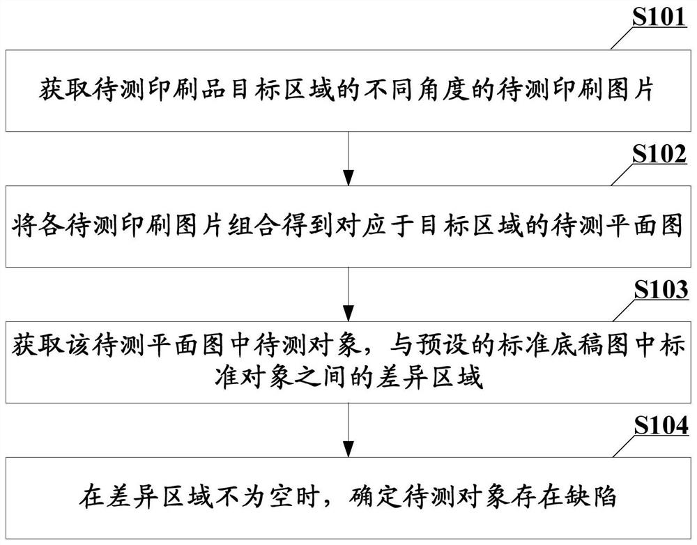
[0029] A defect detection method is provided in the embodiment of the present application, see figure 1 shown, including:

[0030] S101: Obtain printed pictures to be tested at different angles of a target area of ​​the printed product to be tested.

[0031] In the embodiment of the present application, the target area refers to the area containing the object to be tested. For example, when the object to be tested is a printed text on a product label, the target area is the product label area on the printed matter to be tested.

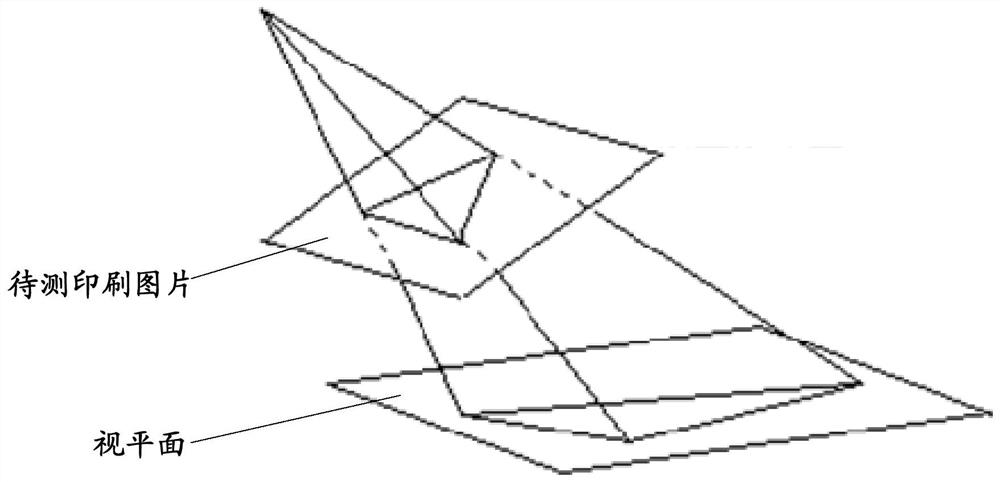
[0032] In the embodiment of the present application, the picture of the printed product to be tested can be obtained by shooting the target area of ​​the printed product to be tested by a camera from different angles, and can also be obtained by rotating the printed product to be tested.

[0033] S102: Combine each printed picture to be tested to obtain a plan view to be tested corresponding to the target area.

[0034] What needs to be understood i...

Embodiment 2

[0069] In this embodiment, on the basis of the first embodiment, the solution of the embodiment of the present application is illustrated by taking the case where the printed matter to be tested is a printed matter in a can and the object to be tested is printed text as an example.

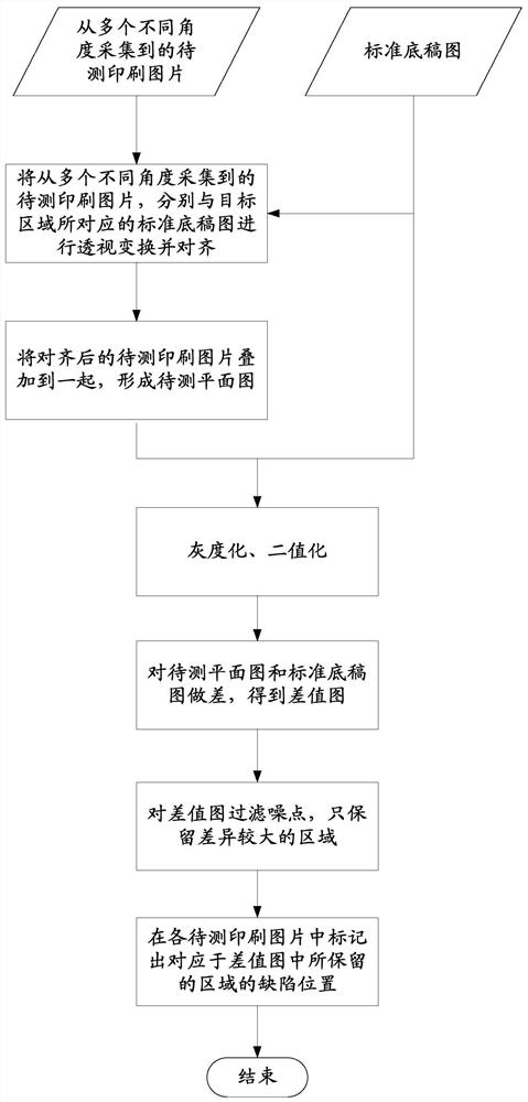
[0070] see image 3 As shown, the defect detection process of the embodiment of the present application includes:

[0071] Step 0. For the area of ​​the canned printed matter that needs to be tested for printing defects (ie, the target area), collect the printing pictures to be tested from multiple different angles.

[0072] The collection of printed pictures to be tested can be realized by placing the canned printed matter at multiple angles for shooting, and it can also be realized by taking pictures of the canned printed matter at the same time with multi-angle cameras.

[0073] At the same time, input the standard draft map corresponding to the target area into the system.

[0074] Step 1. P...

Embodiment 3

[0085] Based on the same inventive concept, an embodiment of the present application also provides a defect detection device. see Figure 4 as shown, Figure 4 A defect detection device 100 corresponding to the method shown in the first embodiment is shown. It should be understood that the specific functions of the defect detection device 100 may refer to the above description, and to avoid repetition, the detailed description is appropriately omitted here. The defect detection device 100 includes at least one software function module that can be stored in a memory in the form of software or firmware or solidified in the operating system of the defect detection device 100 . specifically:

[0086] see Figure 4 As shown, the defect detection device 100 includes: an acquisition module 101 , a combination module 102 and a determination module 103 . in:

[0087] The obtaining module 101 is configured to obtain the printed pictures to be tested at different angles of the targ...


PUM


Abstract

The invention provides a defect detection method and device, electronic equipment and a readable storage medium, and the method comprises the steps: obtaining to-be-detected printed pictures of a target region of a to-be-detected printed matter at different angles, and enabling the target region to contain a to-be-detected object; combining the to-be-tested printed pictures to obtain a to-be-tested planar graph corresponding to the target area, and obtaining a difference area between a to-be-tested object in the to-be-tested planar graph and a standard object in a preset standard manuscript graph by the medium; and when the difference area is not empty, determining that the to-be-detected object has defects. Thus, by obtaining the difference area between the to-be-detected object in the to-be-detected planar graph and the standard object in the preset standard manuscript graph, whether the to-be-detected object has defects or not can be effectively determined. The whole scheme is simple to implement, and compared with a traditional manual detection mode, the cost is lower, the efficiency is high, the detection accuracy is higher, and the method can be effectively suitable for industrial production.

Description

technical field [0001] The present application relates to the technical field of image processing, in particular, to a defect detection method, device, electronic equipment and readable storage medium. Background technique [0002] In real life, there are many situations where corresponding content is printed on non-planar objects, such as canned goods (such as Coca-Cola cans, etc.) printed with ingredients, origin, shelf life and other text. [0003] For the objects on these non-planar printed matter, if the traditional manual detection method is used to realize it, there are disadvantages such as high cost, low efficiency, strong subjectivity, and easy fatigue, which cannot meet the needs of industrial production. Contents of the invention [0004] The purpose of the embodiments of the present application is to provide a defect detection method, device, electronic device and readable storage medium, so as to realize defect detection for objects printed on non-planar prin...

Claims


Application Information

Patent Timeline
Patent Type & Authority Applications(China)
IPC IPC(8): G06T7/00G01N21/956
CPCG01N21/956G06T7/0004G06T2207/10004G06T2207/20024G06T2207/30144
Inventor 汤寅航林国森张发恩
Owner 创新奇智(上海)科技有限公司
Why Eureka
Try Eureka