Shaft connector with overload protection

An overload protection, shaft connector technology, applied in the direction of controlling mechanical energy, electrical components, electromechanical devices, etc., can solve the problems of increasing output, small thermal capacity of new motors, weak overload capacity, etc., to improve overload capacity, avoid Overheating and burning, avoiding the effect of reverse electric braking

Inactive Publication Date: 2020-10-16
合肥左心科技有限公司
View PDF0 Cites 4 Cited by
  • Summary
  • Abstract
  • Description
  • Claims
  • Application Information

AI Technical Summary

Problems solved by technology

[0002] The motor is a very common driving device in daily life. The output power of the motor is determined by the load. When the load of the motor is too heavy, it will cause the motor to be overloaded. Generally, the speed will drop, the motor will heat up, and the ground will be heard. The motor produces damage, and with the advancement of technology, the motor is more likely to burn than in the past: due to the continuous development of insulation technology, the design of the motor requires both an increase in output and a reduction in volume, so that the heat capacity of the new motor is getting smaller and smaller , the overload internal load capacity is getting weaker and weaker
[0003] A common solution to overload is to set a thermal relay on the motor circuit. When the motor is overloaded and heats up, cut off the circuit, stop the motor, and wait for the temperature to recover or restart it manually. However, in some occasions, the motor cannot be stopped or it is inconvenient to stop. Such as wind power generation, when the speed is too fast, it may be overloaded and burned
[0004] Secondly, when the motor is braking with a load, due to the inertia of the load, reverse current braking may occur, causing the current in the motor to be too large. burn

Method used


Image

  • Shaft connector with overload protection
  • Shaft connector with overload protection
  • Shaft connector with overload protection

Examples


Embodiment Construction

[0022] The following will clearly and completely describe the technical solutions in the embodiments of the present invention with reference to the accompanying drawings in the embodiments of the present invention. Obviously, the described embodiments are only some, not all, embodiments of the present invention. Based on the embodiments of the present invention, all other embodiments obtained by persons of ordinary skill in the art without making creative efforts belong to the protection scope of the present invention.

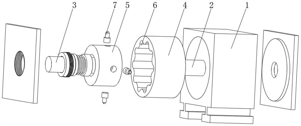
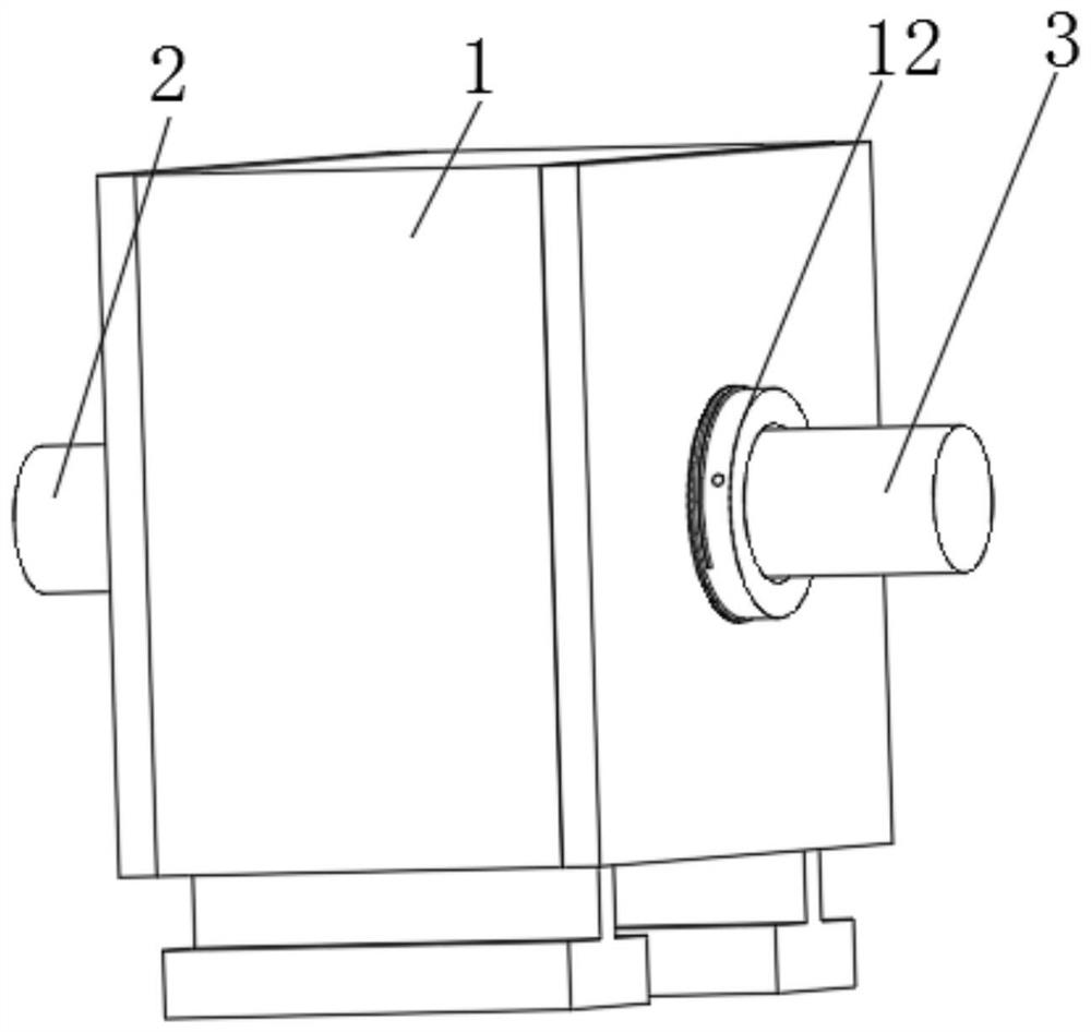
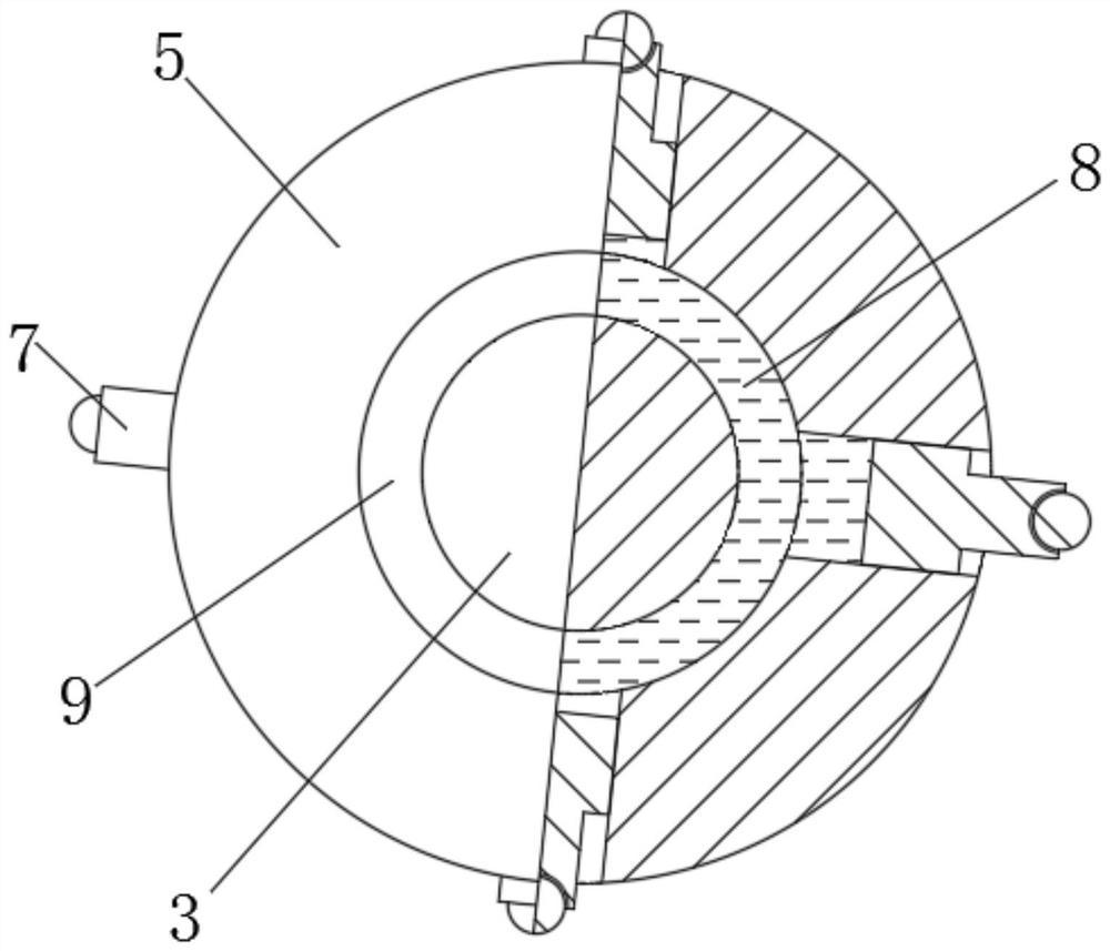
[0023] see Figure 1-2 , a shaft coupling with overload protection, including a housing 1, an output shaft 2 and an input shaft 3, the housing 1 is equipped with front and rear end covers, the output shaft 2 is connected to the input shaft of the load, and the input shaft 3 is connected to the output of the motor Shaft connection, the output shaft 2 is fixedly connected with the driven sleeve 4, the driven sleeve 4 is assembled in the housing 1, the output sha...


PUM


Abstract

The invention relates to the technical field of electromechanical equipment, and discloses a shaft connector with overload protection. The shaft connector comprises a shell, an output shaft and an input shaft, wherein the output shaft is fixedly connected with a driven sleeve, the input shaft is fixedly connected with a driving column, and the driving column is assembled in a concave-convex curvedsurface. According to the invention, by using the principle that the output power of the motor is determined by the load, the maximum output torque of the shaft connector is limited, so that the output torque and power of the motor are limited, overload operation of the motor is avoided, and the overload capacity of the motor is improved; when the motor is overloaded due to self factors, the motor is overloaded, so that the rotating speed is reduced, the centrifugal force is reduced, and the limiting torque of the shaft connector is reduced along with the reduction of the rotating speed so asto make the motor operate in a power reduction manner and reduce the current to avoid the motor from being overheated and burnt; and the concave-convex curved surface and the transmission column slide when the load is overlarge, the reverse input of the load torque is limited, and reverse electric braking caused by inertia is avoided.

Description

[0001] The invention relates to the technical field of electromechanical equipment, in particular to a shaft coupling with overload protection. Background technique [0002] The motor is a very common driving device in daily life. The output power of the motor is determined by the load. When the load of the motor is too heavy, it will cause the motor to be overloaded. Generally, the speed will drop, the motor will heat up, and the ground will be heard. The motor produces damage, and with the advancement of technology, the motor is more likely to burn than in the past: due to the continuous development of insulation technology, the design of the motor requires both an increase in output and a reduction in volume, so that the heat capacity of the new motor is getting smaller and smaller , the overload capacity is getting weaker and weaker. [0003] A common solution to overload is to set a thermal relay on the motor circuit. When the motor is overloaded and heats up, cut off the...

Claims


Application Information

Patent Timeline
Patent Type & Authority Applications(China)
IPC IPC(8): H02K7/00H02K7/102
CPCH02K7/003H02K7/102H02K2213/06
Inventor 陈雪
Owner 合肥左心科技有限公司
Why Eureka
Try Eureka