
Digital TV Transmitter Monitoring System and Its Adaptive Power Balance Regulation Method

A technology of digital TV and monitoring system, applied in the parts of TV system, TV, color TV, etc., can solve the problems of unable to realize intelligent adjustment of power, unable to obtain rapid adjustment, inconsistent gain of power amplifier module, etc. The effect of failure working time, expanding equipment loss and reducing workload

Active Publication Date: 2018-06-29
HAIHUA ELECTRONICS ENTERPRISECHINA CORP
View PDF4 Cites 0 Cited by
  • Summary
  • Abstract
  • Description
  • Claims
  • Application Information

AI Technical Summary

Problems solved by technology

[0004] For high-power TV transmission systems, it is usually necessary to combine multiple power amplifier modules to achieve the required power. In order to ensure the safe operation of the synthesizer, the efficiency of the transmission system and related indicators, the output power of the power amplifier modules participating in the synthesis is required to be consistent. However, due to the batch production of power amplifier tubes and the manufacture and production of power amplifier links, it will inevitably lead to inconsistent gain of the power amplifier modules, which requires an adjustable attenuator to adjust the output power of the power amplifier modules involved in power synthesis
The traditional attenuator adjustment needs to manually compare and judge the gain or output power of the power amplifier modules involved in power synthesis, and then calculate the adjustment amount, and then perform manual adjustment, which cannot realize intelligent power adjustment; especially when the transmitter is working, if the power is not If the balance cannot be adjusted quickly, it may burn out the transmitter and cause interruption of program broadcasting

Method used


Image

  • Digital TV Transmitter Monitoring System and Its Adaptive Power Balance Regulation Method
  • Digital TV Transmitter Monitoring System and Its Adaptive Power Balance Regulation Method
  • Digital TV Transmitter Monitoring System and Its Adaptive Power Balance Regulation Method

Examples


Embodiment 1

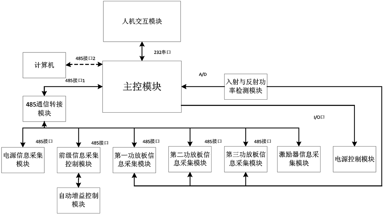
[0050] Such as figure 1 As shown, this embodiment provides a digital TV transmitter monitoring system, which includes a main control module, a human-computer interaction module, an incident and reflected power detection module, a 485 communication adapter module, a power supply control module, and a power supply information collection module , pre-stage information acquisition module, automatic gain control (Automatic Gain Control, AGC) module, exciter information acquisition module and three power amplifier board information acquisition modules, the main control module is connected with the human-computer interaction module, power supply control module and incident It is connected with the reflected power detection module, and is connected with the power supply information acquisition module, the pre-stage information acquisition module, the exciter information acquisition module and the three power amplifier board information acquisition modules respectively through the 485 c...


PUM


Abstract

The invention discloses a digital television transmitter monitoring system and an adaptive power balance adjusting method thereof. The system comprises a master control module, a man-machine interaction module, an incident and reflected power detection module, a 485 communication switching module, a power supply control module, a power supply information acquisition module, a preceding stage information acquisition module, an automatic gain control module, an exciter information acquisition module and a plurality of power amplifier board information acquisition modules. The master control module is connected to the man-machine interaction module, the power supply control module and the incident and reflected power detection module respectively. And the master control module is connected to the power supply information acquisition module, the preceding stage information acquisition module, the exciter information acquisition module and the plurality of power amplifier board information acquisition modules through the 485 communication switching module respectively. The preceding stage information acquisition module is connected to the automatic gain control module. The incident and reflected power detection module is connected to the plurality of power amplifier board information acquisition modules. In the invention, output power of each power amplifier board can be monitored and adjusted in real time and synthesis efficiency is guaranteed.

Description

technical field [0001] The invention relates to a monitoring system, in particular to a digital TV transmitter monitoring system and an adaptive power balance adjustment method thereof, belonging to the research field of radio and TV transmitter power amplifier power control and complete machine monitoring. Background technique [0002] The state of the TV transmitting system is related to the quality of broadcast programs, so ensuring the reliability and stability of the transmitter system is the primary task of the system. Secondly, most of the devices in the launch system are high-power, and its operation needs to follow a set of strict procedures. Once an accident occurs, such as poor heat dissipation or excessive standing wave ratio, it may burn out the equipment. Therefore, the monitoring system must have high real-time performance and a reasonable mechanism for dealing with unexpected situations. [0003] The monitoring system of the launch system has also experience...

Claims


Application Information

Patent Timeline
Patent Type & Authority Patents(China)
IPC IPC(8): H04N17/00H04N5/38
CPCH04N5/38H04N17/004
Inventor 张晓波方晓科孙龙民唐四中高学强
Owner HAIHUA ELECTRONICS ENTERPRISECHINA CORP
Learn More