Rectifier bridge structure
A technology of rectifier bridge and copper wire, which is applied in the direction of transforming equipment structural components, converting AC power input to DC power output, output power conversion device, etc. Bridge production costs and other issues, to achieve the effect of reducing manufacturing cost input, reducing use, and convenient layout
- Summary
- Abstract
- Description
- Claims
- Application Information
AI Technical Summary
Problems solved by technology
Method used
Image

Examples
Embodiment Construction
[0024] The specific implementation manner of the present invention will be described in further detail below by describing the best embodiment with reference to the accompanying drawings.
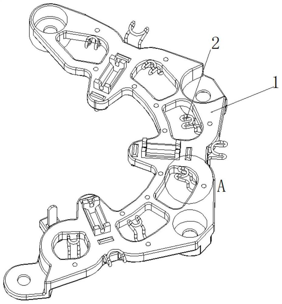
[0025] The rectifier bridge body involved in the present invention is connected to the stator lead wire and the rectifier bridge diode lead wire through the rectifier bridge terminal. Hereinafter, for the convenience of statement, the stator lead wire and the rectifier bridge diode lead wire are collectively referred to as lead wires.
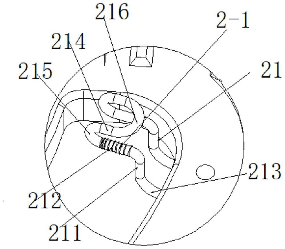
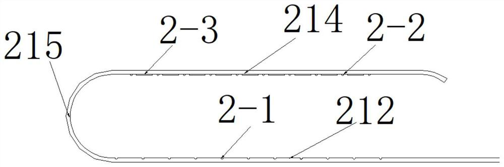
[0026] A rectifier bridge structure, comprising a rectifier bridge body 1; a plurality of rectifier bridge terminals are arranged on the rectifier bridge body 1; the rectifier bridge terminals include copper wire terminals 2 connected with the rectifier bridge body 1; the present invention discloses A rectifier bridge structure. The invention optimizes the rectifier bridge terminals and uses copper wires instead of the original copper plate structure, which f...
PUM
 Abstract
Description
Claims
Application Information