
Injection molded screening apparatuses and methods

A technology of screening and screening area, which is applied in the field of screening materials and screening components, can solve the problems of error-prone, unable to withstand high temperature and complexity, unable to withstand compressive loads, etc., to achieve light weight, simple assembly, and eliminate the need Effect

Pending Publication Date: 2020-10-16
DERRICK CORP
View PDF26 Cites 0 Cited by
  • Summary
  • Abstract
  • Description
  • Claims
  • Application Information

AI Technical Summary

Problems solved by technology

Thus, the conventional polymeric screens cited in U.S. Provisional Application No. 61 / 652,039 are identical to the conventional thermoset polymeric screens cited herein and in U.S. Provisional Patent Application No. 61 / 714,882, and Can be made into extremely small meshes (as described herein and in US Provisional Patent Application No. patent pending), including lack of structural stability and durability, inability to withstand compressive-type loads, inability to withstand high temperatures and complex, time-consuming, error-prone manufacturing methods

Method used


Image

  • Injection molded screening apparatuses and methods
  • Injection molded screening apparatuses and methods
  • Injection molded screening apparatuses and methods

Examples


Embodiment Construction

[0238] In some of the figures, like reference numerals refer to like parts.

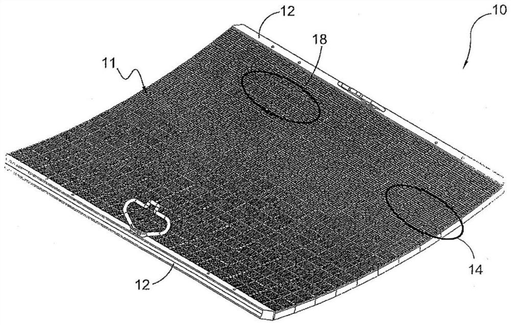
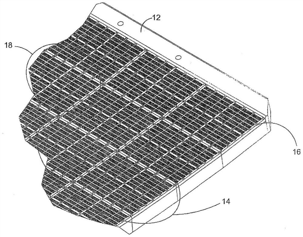
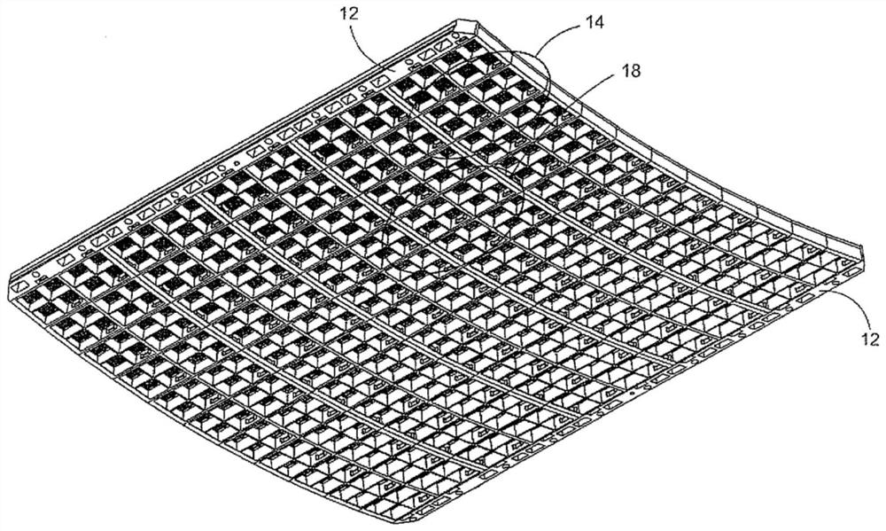
[0239] Embodiments of the present invention provide a screen assembly comprising injection molded screen elements mated with sub-grids. A plurality of sub-grids are fixedly secured to one another to form a vibrating screen assembly having a continuous screening surface configured for use on a vibrating screening machine. The entire screen assembly structure is capable of withstanding severe loading conditions when installed and operated on a vibratory screen machine. Injection molded screen elements offer many benefits in screen assembly manufacturing and vibratory screening applications. In a particular embodiment of the invention, the screen element is injection molded using a thermoplastic material. In some embodiments of the invention, the screen element may have first adhesion means configured to mate with second adhesion means on the sub-grid. The first and second adhering means may comprise...


PUM

PropertyMeasurementUnit
thicknessaaaaaaaaaa
thicknessaaaaaaaaaa
thicknessaaaaaaaaaa

Abstract

Screening members (16), screening assemblies (10), methods for fabricating screening members and assemblies and methods for screening materials are provided for vibratory screening machines that incorporate the use of injection molded materials. Use of injection molded screen elements provide, inter alia, for: varying screening surface (11) configurations; fast and relatively simple screen assembly fabrication; and a combination of outstanding screen assembly mechanical and electrical properties, including toughness, wear and chemical resistance. Embodiments of the present invention use a thermoplastic injection molded material.

Description

[0001] Cross References to Related Applications [0002] This application claims priority to U.S. Patent Application No. 15 / 965,195, filed April 27, 2018, which claims priority to U.S. Provisional Patent Application No. 62 / 648,771, filed March 27, 2018 and is also a continuation-in-part of U.S. Patent Application No. 15 / 851,099 filed December 21, 2017. U.S. Patent Application No. 15 / 851,099 is a divisional application of U.S. Patent Application No. 9,884,344, filed July 5, 2016, No. 15 / 201,865. US Patent Application No. 15 / 201,865, Patent No. 9,884,344 is a continuation of US Patent Application No. 14 / 268,101, Patent No. 9,409,209, filed May 2, 2014. US Patent Application No. 14 / 268,101, filed May 2, 2014, Patent No. 9,409,209 is a continuation-in-part of US Patent Application No. 13 / 800,826, filed March 13, 2013. U.S. Patent Application No. 13 / 800,826, filed March 13, 2013, requires U.S. Provisional Patent Application No. 61 / 714,882, filed October 17, 2012, and U.S. Provision...

Claims


Application Information

Patent Timeline
Patent Type & Authority Applications(China)
IPC IPC(8): B07B1/46B01D29/01
CPCB07B1/4609B07B1/4618B07B1/4645B07B1/469B01D29/01
Inventor 基斯·霍夫斯基
Owner DERRICK CORP
Learn More