Oncomelania tail shearing machine
A shearing machine and snail technology, which is used in the processing of crustaceans, slaughtering, food science, etc., can solve the problems of time-consuming and laborious, manual feeding, etc.
- Summary
- Abstract
- Description
- Claims
- Application Information
AI Technical Summary
Problems solved by technology
Method used
Image
Examples
Embodiment 1
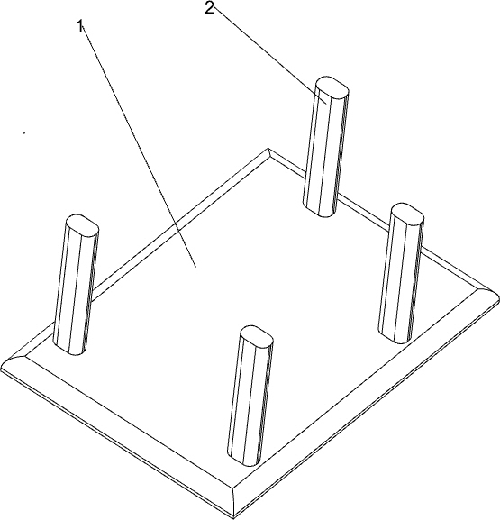
[0071] A screw tail shearer, such as Figure 1-3 As shown, it includes a base 1, a support column 2, a transmission mechanism 3 and a feeding mechanism 4. The base 1 is provided with a support column 2, and a transmission mechanism 3 is connected between the tops of the support columns 2, and a feeding mechanism 3 is connected to the transmission mechanism 3. Institution 4.
[0072] When people need to cut the snail tail, the snails are first placed on the parts of the feeding mechanism 4 respectively, and then the transmission mechanism 3 is started, and the transmission mechanism 3 rotates to drive the parts of the feeding mechanism 4 to push the snails to move to the left, and the snails of the transmission mechanism 3 The part cuts the tail of the snail, and then people take off the snail that has been successfully trimmed. When the equipment is not needed, the transmission mechanism 3 can be closed.
Embodiment 2
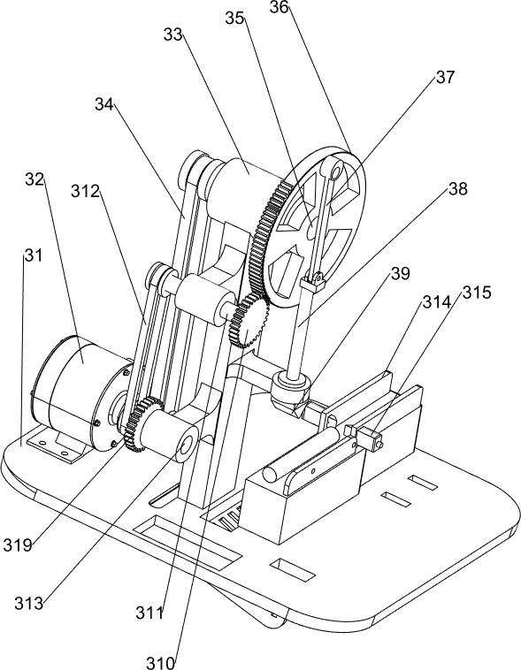
[0074] On the basis of Example 1, such as Figure 4-6 As shown, the transmission mechanism 3 includes a workbench 31, a motor 32, a first bracket 33, a first belt set 34, a first transmission shaft 35, a rotating missing gear 36, a first connecting rod 37, a second connecting rod 38, a cutting Knife 39, first gear 310, second transmission shaft 311, second belt set 312, third transmission shaft 313, discharge platform 314, fixed outer frame 315, first compression spring 316, third connecting rod 317 and push block 318, a workbench 31 is connected between the tops of the support columns 2, a motor 32 is connected to the left side of the rear part of the workbench 31, a first bracket 33 is connected to the left side of the rear part of the workbench 31, and the first bracket 33 is located at the front side of the motor 32, The top of the first support 33 is rotatably connected with the first transmission shaft 35 , the upper left side of the first support 33 is rotatably connect...
Embodiment 3
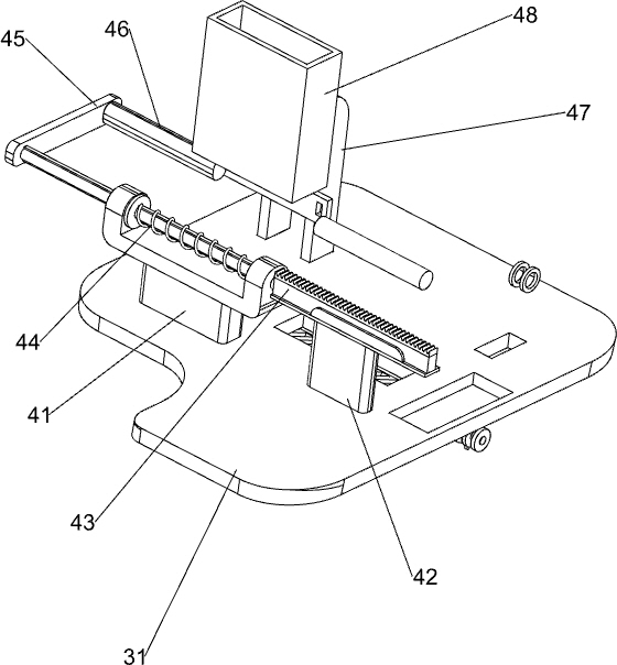
[0077] On the basis of Example 2, such as Figure 7-10 As shown, the feeding mechanism 4 includes a first support block 41, a second support block 42, a rack bar 43, a second compression spring 44, a fourth connecting rod 45, a material push rod 46, a second support 47 and storage Box 48, a first support block 41 is connected to the right rear side of the top of the workbench 31, a second support block 42 is connected to the left rear side of the top of the workbench 31, and the second support block 42 is located between the motor 32 and the first support 33. A rack bar 43 is slidably connected between the upper side of a support block 41 and the upper side of the second support block 42, the rack bar 43 is engaged with the second gear 319, and the right side of the rack bar 43 is connected to the left side of the first support block 41. A second compression spring 44 is connected between them, and the second compression spring 44 is set on the outside of the rack bar 43. The ...
PUM
 Abstract
Description
Claims
Application Information
 - R&D
- Intellectual Property
- Life Sciences
- Materials
- Tech Scout
- Unparalleled Data Quality
- Higher Quality Content
- 60% Fewer Hallucinations
Browse by: Latest US Patents, China's latest patents, Technical Efficacy Thesaurus, Application Domain, Technology Topic, Popular Technical Reports.
© 2025 PatSnap. All rights reserved.Legal|Privacy policy|Modern Slavery Act Transparency Statement|Sitemap|About US| Contact US: help@patsnap.com


