Liquid-diet intake assisting device

A liquid food and inner cavity technology, applied in the direction of therapeutic feeding tubes, etc., can solve the problems of increased blockage of parts, lack of inflow and outflow valves, time-consuming and labor-intensive problems, etc.

Active Publication Date: 2020-10-20
JIANGSU UNIV OF SCI & TECH IND TECH RES INST OF ZHANGJIAGANG
View PDF6 Cites 0 Cited by
  • Summary
  • Abstract
  • Description
  • Claims
  • Application Information

AI Technical Summary

Problems solved by technology

However, in the process of manual operation, the pressure and speed of liquid food will be difficult to accurately control due to the difference in viscosity. On the one hand, it will bring risks and unnecessary pressure to the patient. On the other hand, it will take time and effort and bring a great burden to nursing work.
[0004] Therefore, the electric booster device came into being. Regarding the existing related devices: although some devices are controlled by a motor driven screw, they do not have inflow and outflow valves, and can only achieve one-way one-way boosting. , the operation process is cumbersome
Although some devices can supply at a constant speed, the transmission parts are in direct contact with the food, which increases the possibility of blockage of the parts, increases the difficulty of lubrication of the parts, and requires higher corrosion resistance of the parts
At the same time, for existing devices, the cavity structure is often more complicated, which increases the difficulty of cleaning

Method used


Image

  • Liquid-diet intake assisting device
  • Liquid-diet intake assisting device
  • Liquid-diet intake assisting device

Examples


Embodiment Construction

[0046] The present invention will be described in detail below in conjunction with accompanying drawing and specific embodiment:

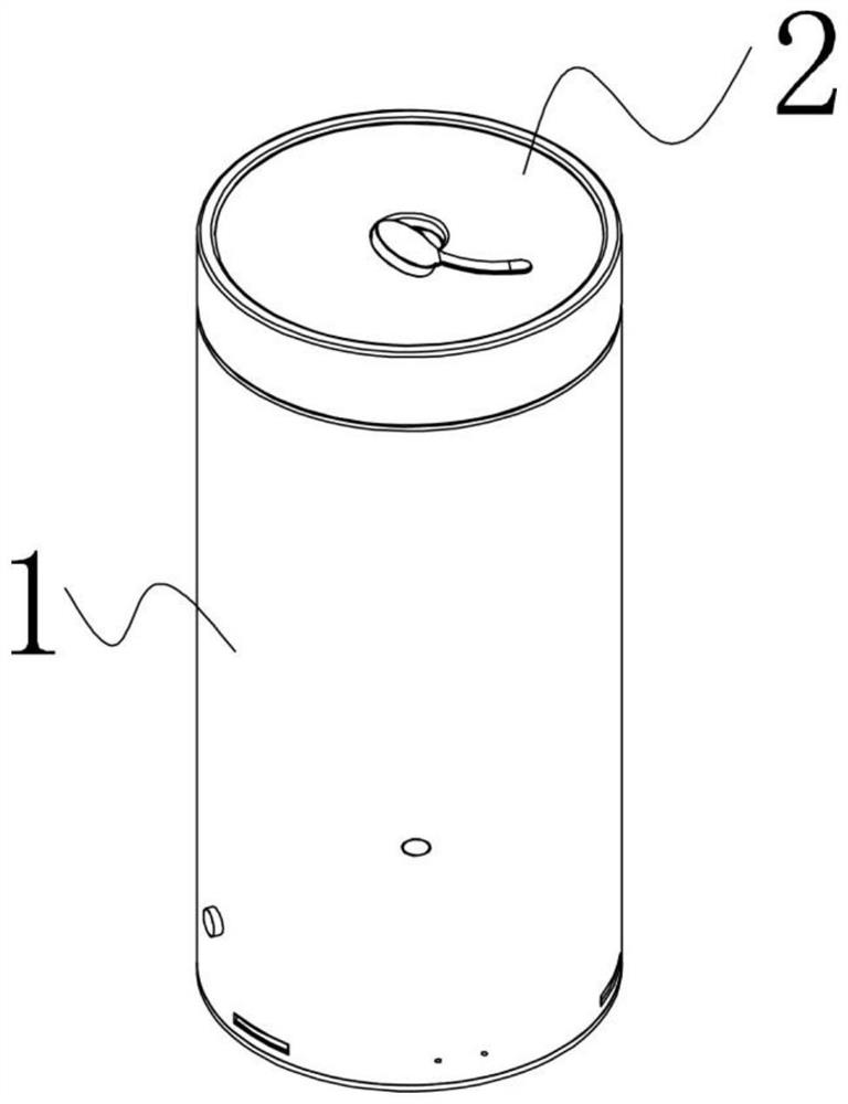
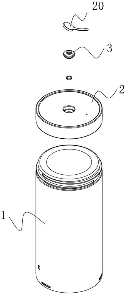
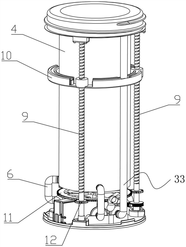
[0047] Such as Figure 1-Figure 9 As shown, an auxiliary liquid food eating device of the present invention includes a cup body 1 and a cup cover 2 sealed on the cup body 1, and a two-way feeding mechanism is arranged in the cup body 1; a first feeding mechanism is provided on the cup cover 2. hole, the first feeding hole is provided with a first one-way valve 3 for one-way flow into the cup cover 2; the cup body 1 includes a shell and an inner cavity 4 for storing liquid food, and the top of the shell and the inner cavity 4 are sealed Setting, the bottom of the inner cavity 4 is provided with a second feeding hole, and the second feeding hole is connected with a feeding tube 6 through a second one-way valve 5 that flows into the inner cavity 4 in one direction, and the feeding tube 6 passes through the housing; two-way The injection mechanism inc...


PUM


Abstract

The invention discloses a liquid-diet intake assisting device. The liquid-diet intake assisting device comprises a cup body and a cup cover, wherein a two-way food injecting mechanism is arranged in the cup body; a first food intake hole is formed in the cup cover, and a first one-way valve with one-way circulation with the interior of the cup cover is arranged in the first food intake hole; the cup body comprises a shell body and an internal cavity for storing liquid diet, the shell body and the top of the internal cavity are arranged in a sealed manner, a second food intake hole is formed inthe bottom of the internal cavity and is connected with a food intake tube through a second one-way valve with one-way circulation with the internal cavity, and the food intake tube threads out the shell body; the two-way food injecting mechanism comprises an internal cavity magnet module, a driving module and an outlet pipeline module, wherein the internal cavity magnet module is arranged in theinternal cavity in a sliding seal manner; the driving module is arranged between the shell body and the internal cavity, and the internal cavity magnet module is driven to reciprocate along the internal cavity through magnetic power; and the outlet pipeline module communicates with the bottom and top of the internal cavity separately, and the liquid diet flows out from the bottom or top of the internal cavity at a uniform speed through the outlet pipeline module.

Description

technical field [0001] The invention relates to the technical field of feeding aids, in particular to a device for assisting feeding with liquid food. Background technique [0002] Some patients have difficulty in ingesting food independently due to diseases such as essential tremor or inconvenient movement after surgery, and need to complete eating with the help of family members or medical staff. Currently clinically, intravenous injection is often used to supply nutrients and rely on artificial liquid food feeding to supplement the nutrients needed by patients. [0003] For intravenous injection, most of the nutrients supplemented during the process are far from enough, and it will also increase the economic burden on the patient's family and the patient's own physical pain. For the method of artificial liquid food feeding, rely on artificially to promote the needle tube of large caliber to help food more. However, in the process of manual operation, the pressure and sp...

Claims


Application Information

Patent Timeline
Patent Type & Authority Applications(China)
IPC IPC(8): A61J15/00
CPCA61J15/0076A61J15/00
Inventor 黄帅博郦远哲方海峰张均华薛伟曹晋李洋刘群董硕王振丁亮蔡李花
Owner JIANGSU UNIV OF SCI & TECH IND TECH RES INST OF ZHANGJIAGANG
Why Eureka
Try Eureka