An auxiliary liquid food feeding device

A liquid food, lumen technology, applied in the direction of therapeutic feeding tubes, etc., can solve the problems of difficult to accurately control the pressure and speed of liquid food, high requirements for corrosion resistance of parts, and no inflow and outflow valves, so as to ensure smoothness, Compact structure design, compact structure effect

Active Publication Date: 2022-08-02
JIANGSU UNIV OF SCI & TECH IND TECH RES INST OF ZHANGJIAGANG
View PDF1 Cites 0 Cited by
  • Summary
  • Abstract
  • Description
  • Claims
  • Application Information

AI Technical Summary

Problems solved by technology

However, in the process of manual operation, the pressure and speed of liquid food will be difficult to accurately control due to the difference in viscosity. On the one hand, it will bring risks and unnecessary pressure to the patient. On the other hand, it will take time and effort and bring a great burden to nursing work.
[0004] Therefore, the electric booster device came into being. Regarding the existing related devices: Although some devices are controlled by a motor-driven screw, they do not have inflow and outflow valves, and can only achieve single-way one-way boosting, and only the same port can be used to enter and exit. , the operation process is cumbersome
Although some devices can supply at a constant speed, the transmission parts are in direct contact with the food, which increases the possibility of blockage of the parts, increases the difficulty of lubrication of the parts, and requires higher corrosion resistance of the parts
At the same time, for existing devices, the cavity structure is often more complicated, which increases the difficulty of cleaning

Method used


Image

  • An auxiliary liquid food feeding device
  • An auxiliary liquid food feeding device
  • An auxiliary liquid food feeding device

Examples


Embodiment Construction

[0046] The present invention will be described in detail below in conjunction with the accompanying drawings and specific embodiments:

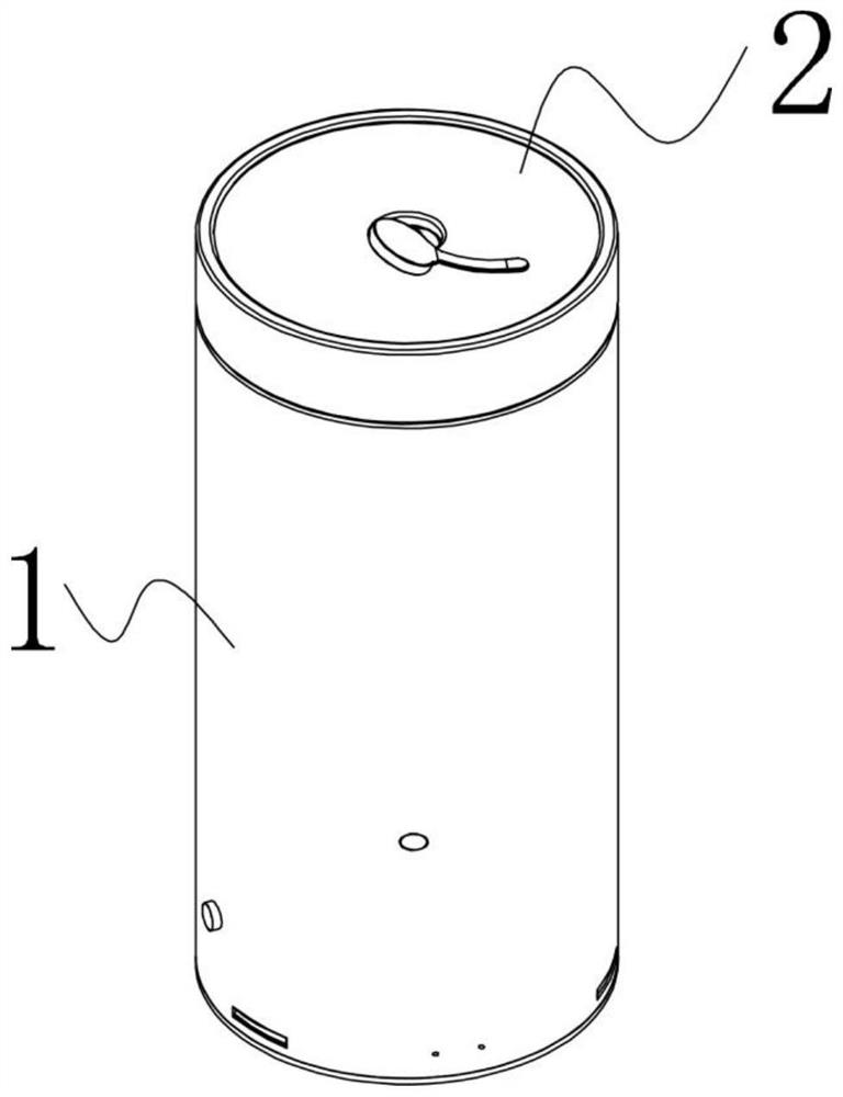
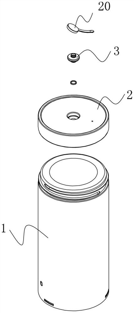
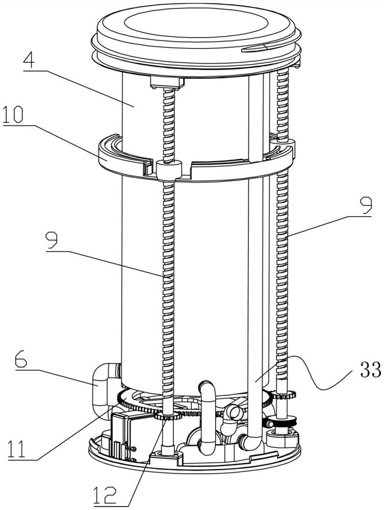
[0047] like Figure 1-Figure 9 As shown, an auxiliary liquid food feeding device of the present invention includes a cup body 1 and a cup cover 2 sealed on the cup body 1. The cup body 1 is provided with a two-way feeding mechanism; the cup cover 2 is provided with a first feeding mechanism. The first feeding hole is provided with a first one-way valve 3 for one-way flow into the cup cover 2; the cup body 1 includes a shell and an inner cavity 4 for storing liquid food, and the top of the shell and the inner cavity 4 is sealed Setting, the bottom of the inner cavity 4 is provided with a second feeding hole, the second feeding hole is connected with a feeding tube 6 through a second one-way valve 5 that flows into the inner cavity 4 in one direction, and the feeding tube 6 passes through the shell; The feeding mechanism includes an inner cavi...


PUM


Abstract

The invention discloses an auxiliary liquid food feeding device, comprising a cup body and a cup cover, a bidirectional feeding mechanism is arranged in the cup body; a first feeding hole is opened on the cup cover, and a one-way direction into the cup cover is arranged in the first feeding hole The first one-way valve for circulation; the cup body includes a shell and an inner cavity for storing liquid food, the top of the shell and the inner cavity is sealed, and the bottom of the inner cavity is provided with a second feeding hole, and the second feeding hole passes through the inward The second one-way valve with one-way circulation in the cavity is connected with a feeding tube, and the feeding tube goes out from the housing; the two-way feeding mechanism includes an inner cavity magnet module, a driving module and an outlet pipeline module; wherein the inner cavity magnet module is slidably sealed. In the inner cavity; the drive module is arranged between the housing and the inner cavity, and drives the inner cavity magnet module to reciprocate along the inner cavity through magnetic force; the outlet pipeline module is respectively connected with the bottom and top of the inner cavity, when the inner cavity magnet module moves along When the inner cavity reciprocates, the liquid food flows out at a constant speed from the bottom or top of the inner cavity through the outlet pipeline module.

Description

technical field [0001] The invention relates to the technical field of assisted feeding, in particular to an assisted liquid food feeding device. Background technique [0002] Some patients have difficulty in ingesting food on their own due to diseases such as essential tremor or inconvenience of movement after surgery, and need to complete the meal with the help of family members or medical staff. At present, intravenous injection of nutrients and artificial liquid feeding are mostly used in clinical practice to supplement the nutrients needed by patients. [0003] For intravenous injection, most of the nutrients supplemented during the process are far from enough, and at the same time, it will also increase the economic burden of the patient's family and the patient's own physical pain. For the method of artificial liquid feeding, it is mostly relying on artificially pushing a large-diameter needle to assist feeding. However, in the process of manual operation, the press...

Claims


Application Information

Patent Timeline
Patent Type & Authority Patents(China)
IPC IPC(8): A61J15/00
CPCA61J15/0076A61J15/00
Inventor 黄帅博郦远哲方海峰张均华薛伟曹晋李洋刘群董硕王振丁亮蔡李花
Owner JIANGSU UNIV OF SCI & TECH IND TECH RES INST OF ZHANGJIAGANG
Why Eureka
Try Eureka