Deicing device, system and method for aircraft wing

A wing and aircraft technology, applied in the field of deicing devices for aircraft wings, can solve the problems of long deicing time and large energy consumption

Inactive Publication Date: 2020-10-20
SHANDONG UNIV
View PDF5 Cites 3 Cited by
  • Summary
  • Abstract
  • Description
  • Claims
  • Application Information

AI Technical Summary

Problems solved by technology

The inventor found that although this anti-icing technology can prevent and dei

Method used


Image

  • Deicing device, system and method for aircraft wing
  • Deicing device, system and method for aircraft wing
  • Deicing device, system and method for aircraft wing

Examples


Embodiment 1

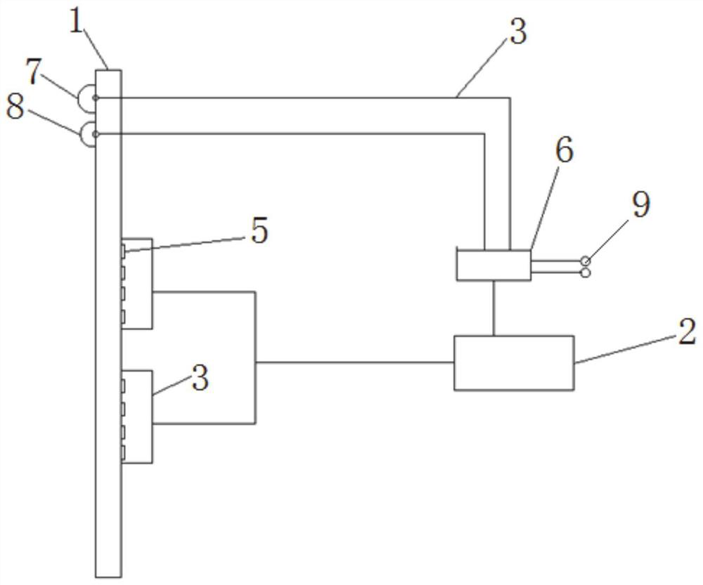
[0036] Embodiments of the present invention provide a deicing device for aircraft wings, such as figure 1 As shown, it includes at least one deicing unit, and also includes a precision pulse generator 2, a temperature sensor 7, a thickness detector 8, a controller 6, a power supply 9, and the temperature sensor 7 is used to detect the atmospheric temperature near the outer edge of the aircraft wing profile, the thickness The detector 8 is used to detect the thickness of the ice layer on the outer surface of the skin.

[0037] The deicing unit is connected to the precision pulse generator 2 through the connection cable 3 , the precision pulse generator 2 , the temperature sensor 7 , and the thickness detector 8 are respectively connected to the controller 6 through the connection cable 3 , and the controller 6 is connected to the power supply 9 . The controller 6 controls the operation / stopping of the precision pulse generator 2 according to the temperature signal fed back by t...

Embodiment 2

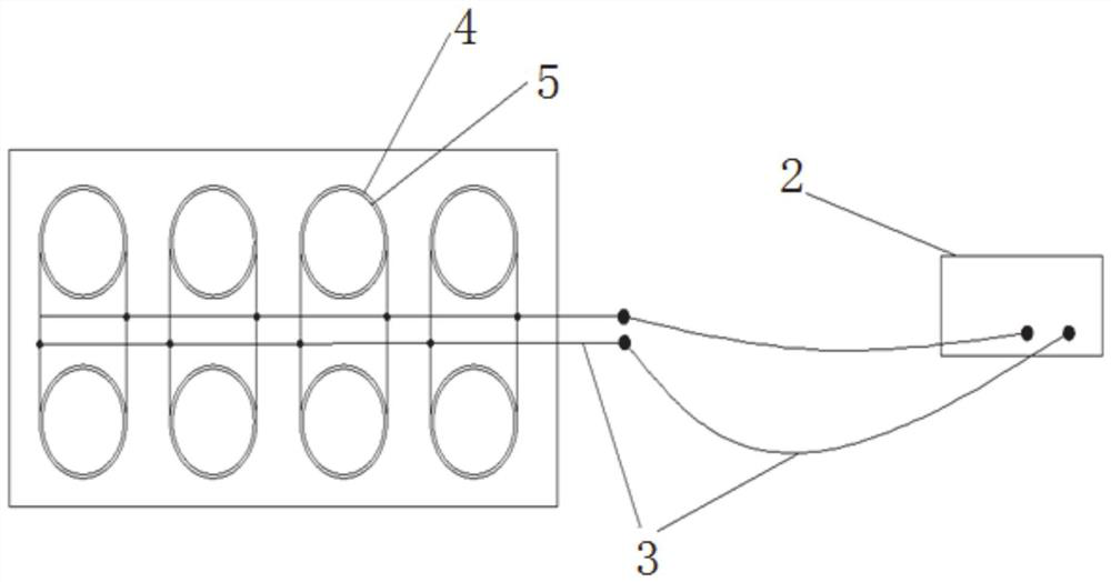
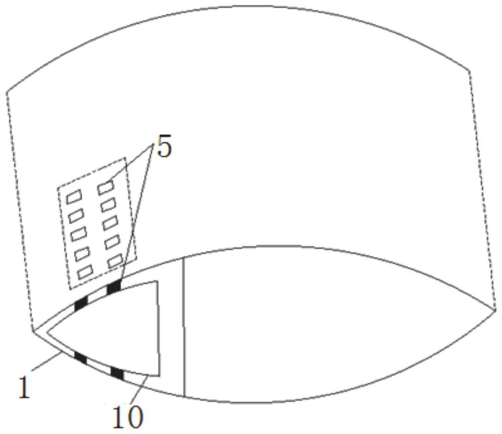
[0044] This embodiment provides a deicing system for aircraft wings, including the deicing device described in Embodiment 1, such as figure 1 with image 3 As shown, the deicing unit is fixed on the inner surface of the airfoil outer skin 1 ; wherein, the outer skin of the wing is the airfoil outer skin 1 , and the inner skin of the wing is the airfoil inner skin 10 .

[0045] When there are multiple deicing units, they are arranged at intervals along the length direction of the airfoil outer skin 1 . In this embodiment, the deicing units are arranged in matrix on various parts of the inner surface of the airfoil outer skin 1 by means of riveting or gluing according to the thickness of the ice layer of the aircraft wing. The temperature sensor 7 and the thickness detector 8 are installed on the outer surface of the airfoil outer skin 1 .

Embodiment 3

[0047] This embodiment also provides a method for deicing an aircraft wing, using the deicing system described in Embodiment 2, comprising:

[0048] The temperature sensor 7 detects the ambient air temperature in real time, and the controller 6 controls the operation / stopping of the precision pulse generator 2 according to the signal transmitted by the temperature sensor 7 . When the atmospheric temperature near the outer edge of the airfoil exceeds the freezing point by 5-10 degrees Celsius, the controller 6 will automatically turn on the precision pulse generator 2, and change the power of the precision pulse generator 2 in time according to the icing thickness signal provided by the thickness detector 7 And the working quantity of the deicing unit (including the electromagnetic coil 4 and the transducer 5).

[0049] The precision pulse generator 2 is connected to the deicing unit through the connection cable 3 and provides matching high-frequency pulses. Under the excitatio...


PUM


Abstract

The invention discloses a deicing device, system and method for an aircraft wing. According to the technical scheme, the deicing device comprises at least one deicing unit; the deicing unit comprisesa plurality of groups of transducers, and each group comprises two transducers; an electromagnetic coil sleeves the outer side of each group of transducers, the electromagnetic coils are connected inparallel and are connected with a precision pulse generator, and the precision pulse generator is connected with a controller; the controller is further connected with a temperature sensor and a thickness detector. By means of high-frequency oscillation of the giant magnetostrictive material and generated instant high-heat-density anti-icing and de-icing, an ice layer at a specific part of a wingin the flying process of an airplane can be effectively removed in real time; and the deicing time is shortened and the energy consumption is greatly reduced while the flight safety of the aircraft iseffectively ensured.

Description

technical field [0001] The invention relates to the field of aircraft deicing, in particular to a deicing device, system and method for aircraft wings. Background technique [0002] Aircraft flying in cold and humid air, such as clouds, wet snow, freezing rain, fog, and high-humidity air with a temperature around zero degrees Celsius, the surface of the body, the leading edge of the wing, and other parts of the aircraft may have different degrees of damage. freeze. A large number of theoretical calculations, wind tunnel tests and flight tests have shown that if there are no anti-icing / de-icing measures for aircraft components, the icing of these components can lead to serious deterioration of aircraft aerodynamic characteristics and stability characteristics, and ultimately have a serious impact on flight safety , such as the reduction of lift, the increase of drag, the reduction of stall angle of attack, and the separation of the boundary layer in advance. [0003] To ove...

Claims


Application Information

Patent Timeline
IPC IPC(8): B64D15/12B64D15/20B64D15/22
CPCB64D15/12B64D15/20B64D15/22
Inventor 陈龙张景奎徐福泉程健男
Owner SHANDONG UNIV
Why Eureka
Try Eureka