Lifting device and application method thereof

A technology for lifting devices and lifting brackets, which is applied in the direction of lifting devices, lifting frames, etc., and can solve the problems of too many auxiliary tools, non-compliance, and inability to do first-in-first-out

Pending Publication Date: 2020-10-20
吉林省亿兆科技有限公司
View PDF0 Cites 1 Cited by
  • Summary
  • Abstract
  • Description
  • Claims
  • Application Information

AI Technical Summary

Problems solved by technology

[0002] At present, the total weight of the shelves after they are full is about 10Kg in production, and it takes a long time for the production line operators to carry them back and forth; because there are many girls on the production line, relatively speaking, the physical energy consumption is relatively large; the fully loaded shelves are uniformly distributed by the material staff, because There is more than one shelf during distribution, and the production line operators can take it at will, and the principle of first-in-first-out cannot be followed; the shelves are transported back and forth, and there are many auxiliary tooling (such as storage racks, back-and-forth transport vehicles, etc.) Most storage racks are non-adjustable in height, which is not ergonomic

Method used


Image

  • Lifting device and application method thereof
  • Lifting device and application method thereof
  • Lifting device and application method thereof

Examples


Embodiment 1

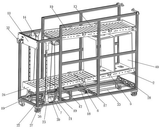
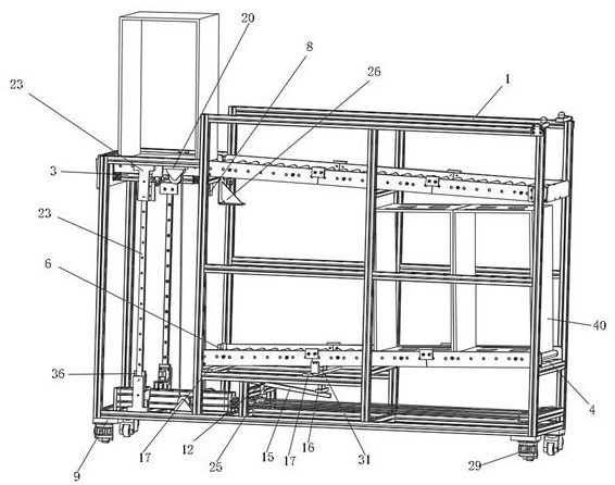
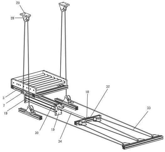
[0019] Such as Figures 1 to 3Shown, a kind of lifting device comprises frame 1, is divided into three layers in frame 1, and one side short side of bottom is provided with three transverse fixed pulleys 28, is provided with on the two crossbeams of frame 1 opposite to it. Two cylinder fixing plates 19 are fixed cylinder 30, and one end of cylinder piston rod 34 connects the inside of cylinder 30, and the other end of cylinder piston rod 34 connects cylinder connection block 18, and cylinder connection block 18 is fixed on the movable pulley block 37, and on the cylinder 30 The frame 1 on both sides of the long surface is provided with two lower pulley fixing plates 21 and is equipped with fixed pulleys 28, and the upper frame 1 opposite to the lower pulley fixing plates 21 is provided with two upper pulley fixing plates 20 and is equipped with fixed pulleys. The pulley 28 is provided with two height stops 14 on the left side of the two upper pulley fixed plates 20, and is pro...


PUM


Abstract

The invention provides a lifting device. The lifting device comprises a frame. The interior of the frame is divided into three layers. Three transverse fixed pulleys are arranged on the short side ofone side of the bottommost layer of the frame, and two cylinder fixing plates are arranged on two cross beams on the side, opposite to the short side, of the frame and used for fixing a cylinder. Oneend of a cylinder piston rod is connected with the interior of the cylinder, and the other end of the cylinder piston rod is connected with a cylinder connecting block. The cylinder connecting block is fixed to a movable pulley set. Two lower pulley fixing plates are arranged in the positions, on the two sides of the long surface of the cylinder, of the frame, and fixed pulleys are arranged on thelower pulley fixing plates. Two upper pulley fixing plates are arranged in the positions, opposite to the lower pulley fixing plates, of the upper portion of the frame, and fixed pulleys are arrangedon the two pulley fixing plates. Two height stop blocks are arranged on the left side of the two upper pulley fixing plates. Two guide rail fixing seats are arranged on the left side of the two height stop blocks. Two guide rail fixing seats are arranged in the positions, opposite to the two guide rail fixing seats at the upper end, of the lower portion of the frame. Two guide rails are arrangedin the four guide rail fixing seats. Each guide rail is provided with a sliding block. The inner side of each sliding block is provided with a sliding block fixing seat.

Description

technical field [0001] The invention relates to a lifting device and a using method thereof, belonging to the field of production technology equipment. Background technique [0002] At present, the total weight of the shelves after they are full is about 10Kg in production, and it takes a long time for the production line operators to carry them back and forth; because there are many girls on the production line, relatively speaking, the physical energy consumption is relatively large; the fully loaded shelves are uniformly distributed by the material staff, because There is more than one shelf during distribution, and the production line operators can take it at will, and the principle of first-in-first-out cannot be followed; the shelves are transported back and forth, and there are many auxiliary tooling (such as storage racks, back-and-forth transport vehicles, etc.) Most storage racks are non-adjustable in height, which does not conform to ergonomic principles. Conten...

Claims


Application Information

Patent Timeline
IPC IPC(8): B66F7/04B66F7/28
CPCB66F7/04B66F7/28
Inventor 刘锋
Owner 吉林省亿兆科技有限公司
Why Eureka
Try Eureka