

Posture changing device and posture changing method for component
A technology for components and workpieces, which is applied in the field of position-changing devices for components, can solve problems such as errors that are prone to occur, and achieve the effects of improving work rhythm, smooth connection, and simple structure
- Summary
- Abstract
- Description
- Claims
- Application Information
AI Technical Summary
Problems solved by technology
Method used
Image

Examples
Embodiment 1
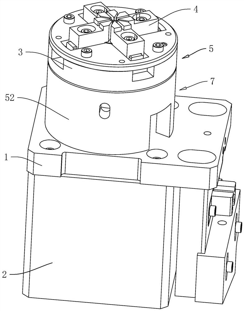
[0047] Embodiment 1, with reference to figure 1 The attitude changing device for components includes a frame 1, a drive motor 2, a turntable 3 and an adsorption piece 7. Specifically, the drive motor 2 is fixed on the frame 1 by bolts, and the output shaft of the drive motor 2 is vertically facing above; the turntable 3 is coaxially fixedly sleeved on the output shaft of the drive motor 2, and the upper surface of the turntable 3 is used to place workpieces, so when the workpiece comes out of the previous process, the workpiece can be placed on the center of the upper surface of the turntable 3 position, then the turntable 3 is rotated by a predetermined angle by driving the motor 2 to change the workpiece to the posture required for the next process, and then the workpiece can be removed from the turntable 3 and sent to the next process.
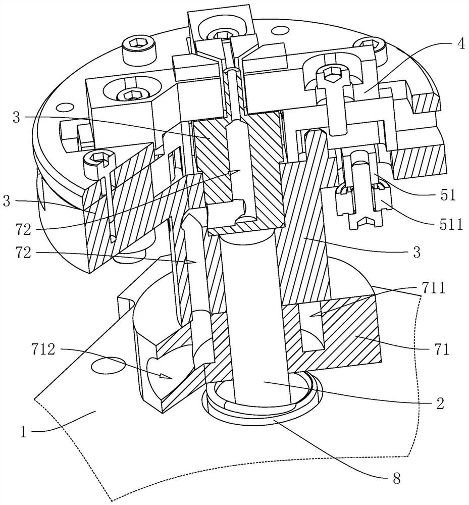
[0048] refer to figure 1 and figure 2 , the adsorption piece 7 includes a fixed block 71 and a flow channel 72 opened on the turntable ...
Embodiment 2
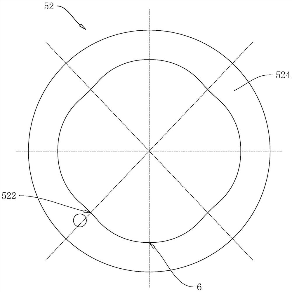
[0067] Embodiment 2, with reference to figure 2 and Figure 4, the difference from Embodiment 1 is that there are four push blocks 4, and the angle between the four push blocks 4 is 90°, if the angle of rotation of the turntable 3 is less than 90° but is a multiple of 90° For example, if the rotation angle of the turntable 3 is 45°, in this embodiment, the guide plate 52 includes four main guides 524 and four compensating guides 525, four main guides 524 and four compensating guides 525 makes the guide plate 52 a closed circular tube, wherein the guide plate 52 is evenly distributed along the circumferential direction with a plurality of far rest positions 6 and a plurality of correction positions 522, and the angle between adjacent far rest positions 6 is 45°, The included angle between adjacent calibration positions 522 is 45°, so that the tracks where the four abutting blocks 51 abut against the guide plate 52 also overlap on the same horizontal plane.
[0068] refer to ...
Embodiment 3
[0070] Embodiment 3, with reference to figure 2 and Figure 5 , the difference from Embodiment 1 is that when the angle between adjacent push blocks 4 is inconsistent with the angle of rotation of the turntable 3 and is not a multiple of each other, if the angle of rotation of the turntable 3 is still a multiple of 360° , the guide plate 52 can still be in the shape of a closed tube, which will be demonstrated with an example next.
[0071] refer to figure 2 and Figure 5 , if the workpiece is in the shape of a triangular prism, there are three push blocks 4, the angle between adjacent push blocks 4 is 120°, and the angle at which the turntable 3 rotates is 90°, and for the convenience of description, when the turntable 3 does not move, The projections of the positions where the three abutting blocks 51 abut against the guide plate 52 on the horizontal plane are set to A, B and C, so as to reflect the relative positional relationship between the three abutting blocks 51, ...
PUM
 Abstract
Description
Claims
Application Information