An automatic screw-tightening device

A screw-tightening and automatic technology, which is applied in metal processing equipment, metal processing, manufacturing tools, etc., can solve problems that affect the efficiency of object combination, complex equipment structure, and low work efficiency, so as to achieve flexible switching of space positions, reduce cumbersomeness, and cost little effect

Active Publication Date: 2018-09-28
SHENYANG SIASUN ROBOT & AUTOMATION +1
View PDF6 Cites 0 Cited by
  • Summary
  • Abstract
  • Description
  • Claims
  • Application Information

AI Technical Summary

Problems solved by technology

The structure of this equipment is complex, the work efficiency is low, and the performance is average, especially the distance between the screw locking module and the screw supply module is far away, which will cause the screw locking module to move to the screw supply module to take out one in each working cycle. Screws, and then return to the work object to complete the screw locking, long travel, time-consuming, poor continuity, seriously affecting the combination efficiency of objects, not suitable for mass and rapid production fields

Method used


Image

  • An automatic screw-tightening device
  • An automatic screw-tightening device
  • An automatic screw-tightening device

Examples


Embodiment Construction

[0021] The specific embodiment of the present invention will be further described below in conjunction with accompanying drawing:

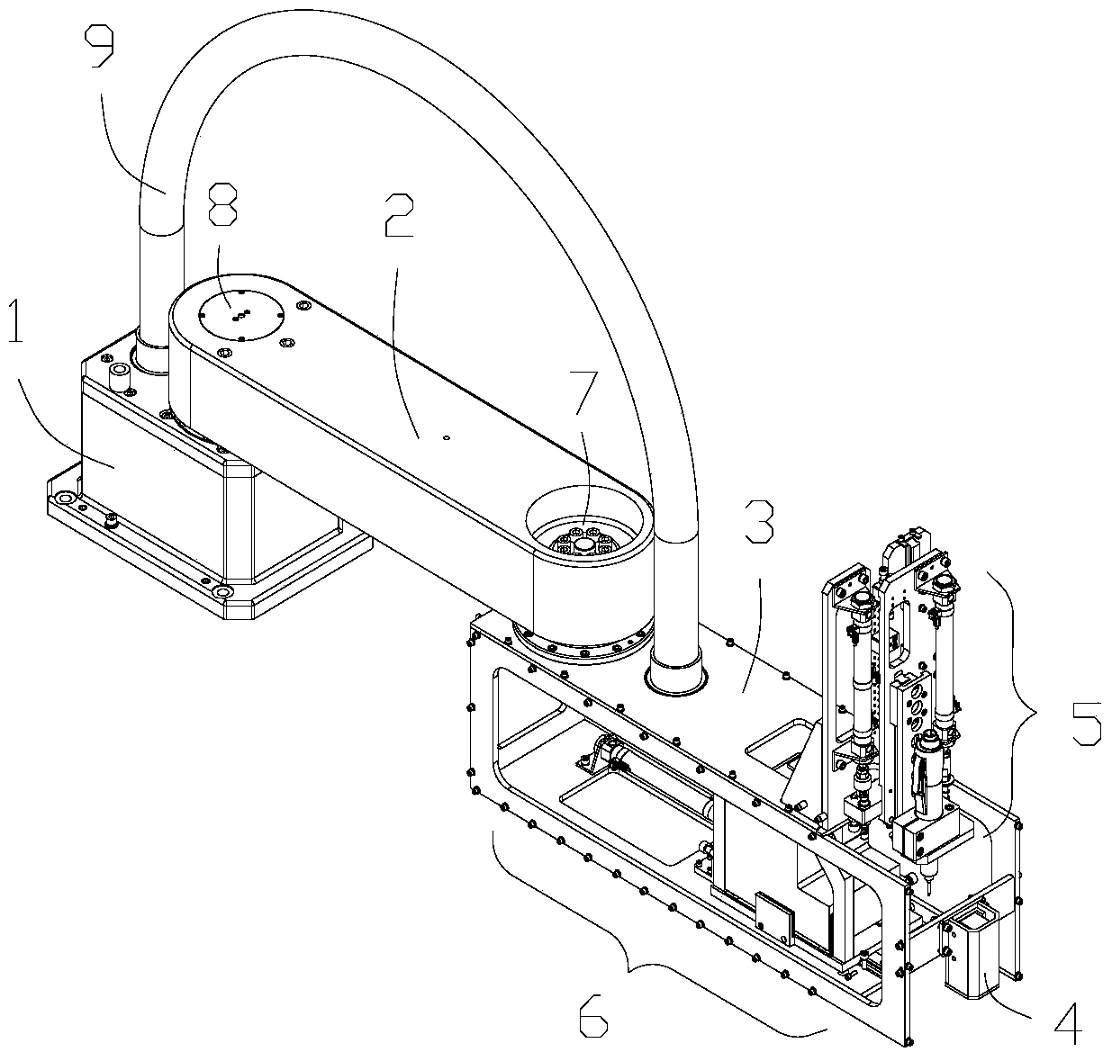
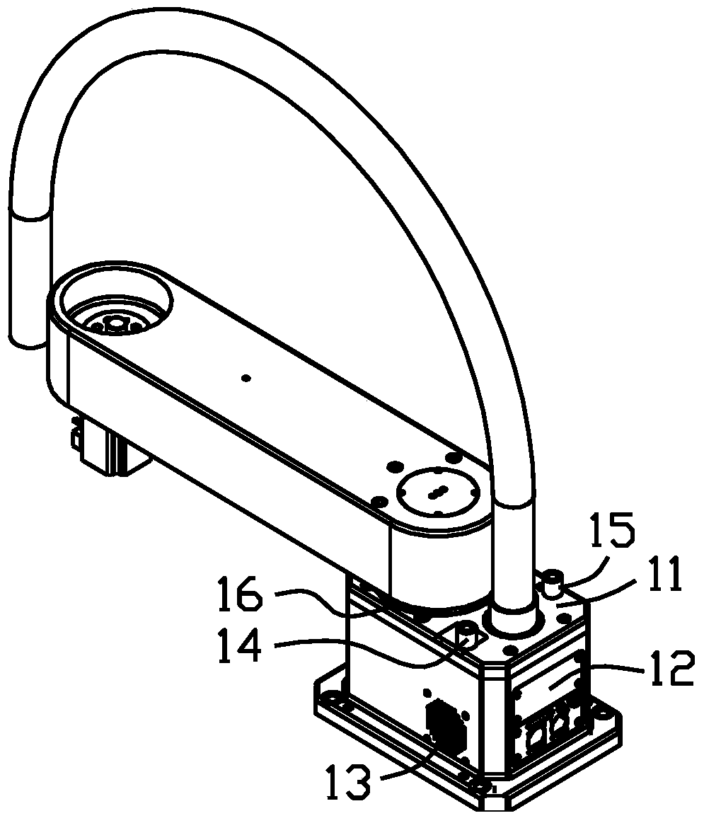
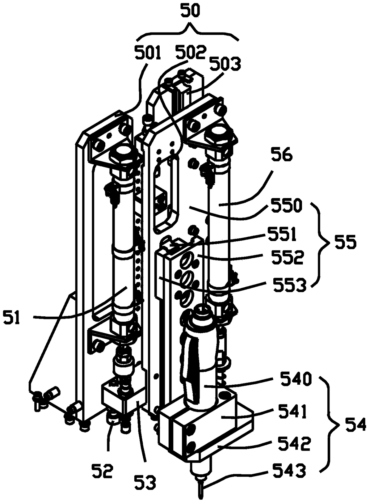
[0022] Such as Figure 1-7 As shown, an automatic screwing device includes a base 1, a boom 2 and a forearm 3, the upper end of the base 1 is provided with a boom 2, and the front end of the boom 2 is connected with the forearm 3; in order to increase the working coverage area, the base 1 and the forearm 3 The connection between the boom 2, the boom 2 and the forearm 3 is realized through the flexibility of the second motor 8 and the first motor 7 respectively, wherein the forearm 3 can rotate around the boom 2, and the boom 2 can rotate around the base 1, There is a wiring hose 9 between the base 1 and the forearm 3, the lower end of the forearm 3 is provided with a nail feeding mechanism 6, the upper end of the forearm 3 is provided with a nailing mechanism 5, and the front end of the nailing mechanism is provided with a visual camera 4, which i...


PUM


Abstract

The invention belongs to the field of automatic mechanical equipment, and particularly relates to an automatic screw turning device. The automatic screw turning device comprises a base, a big arm and a small arm. One end of the big arm is mounted at the upper end of the base, and the other end of the big arm is connected with the small arm. The base and the big arm are flexibly connected through a second motor, and the big arm and the small arm are flexibly connected through a first motor. A wiring hose is arranged between the base and the small arm. A screw supply mechanism is arranged at the lower end of the small arm, a screw turning mechanism is arranged at the upper end of the small arm, and a visual camera is arranged at the front end of the screw turning mechanism. Mechanical locating is utilized in the mechanisms, locating is accurate, and complexity brought by electric control is reduced; and the screw turning mechanism only ascends and descends vertically, the screw supply mechanism only advances horizontally, a servo air cylinder structure is adopted, implement is easy, cost is low, in addition, the distance between the screw turning mechanism and the screw supply mechanism is short, space position switching is flexible, and the work cycle can be improved easily.

Description

technical field [0001] The invention belongs to the field of automatic mechanical equipment, and in particular relates to an automatic screw screwing device. Background technique [0002] At present, many parts such as circuit boards, peripheral shells, and internal structures of electronic equipment that are common in industrial production need to be fixed and locked with a large number of screws. Automatic screw screwing equipment has emerged as the times require, which greatly improves production efficiency. Reduced labor costs. [0003] The invention patent with application number 201210185847.2 provides an automatic locking screw device. The invention completes the determination of the screw hole position, screw locking and locking correctness inspection through the image observation module, screw locking module and locking inspection module respectively. Thereby locking at least one screw into a screw hole on a working object is realized. The structure of this equipm...

Claims


Application Information

Patent Timeline
Patent Type & Authority Patents(China)
IPC IPC(8): B23P19/06
CPCB23P19/066
Inventor 朱维金王金涛曲道奎徐方李学威王宏玉
Owner SHENYANG SIASUN ROBOT & AUTOMATION
Why Eureka
Try Eureka