
Double-rotor rotary piston engine

A rotary piston and double rotor technology, applied to internal combustion piston engines, combustion engines, machines/engines, etc., can solve problems such as high power consumption, small horsepower volume ratio, and large vibration

Active Publication Date: 2012-01-18
王尚锋
View PDF6 Cites 11 Cited by
  • Summary
  • Abstract
  • Description
  • Claims
  • Application Information

AI Technical Summary

Problems solved by technology

Piston work cannot be converted into torque very efficiently
[0004] 2. The reciprocating piston engine must be equipped with a complex valve mechanism, which consumes a lot of power and makes a lot of noise
[0005] 3. The reciprocating piston engine piston reciprocates, the piston inertia is difficult to eliminate, and the vibration is large
[0006] 4. The cylinder volume of the reciprocating piston engine is constant, and the intake air volume and compression ratio cannot be effectively controlled
[0007] 5. The reciprocating piston engine does work once every two revolutions, and the horsepower volume ratio is small
After the engine has been used for a period of time, it is easy to cause air leakage due to the wear of the oil seal material, which greatly increases fuel consumption and pollution
Its unique mechanical structure also makes this type of engine more difficult to repair
[0010] 2. When the triangular rotor engine is doing work, due to the shape and position of the rotor, there is a certain recoil angle, which consumes a lot of energy
[0011] 3. The cylinder volume of the triangular rotor engine is constant, and the intake air volume and compression ratio cannot be effectively controlled
Therefore, the power is increased

Method used


Image

  • Double-rotor rotary piston engine
  • Double-rotor rotary piston engine
  • Double-rotor rotary piston engine

Examples


Embodiment Construction

[0083] 1. Introduction of main components

[0084] 1. A cylinder head (1)

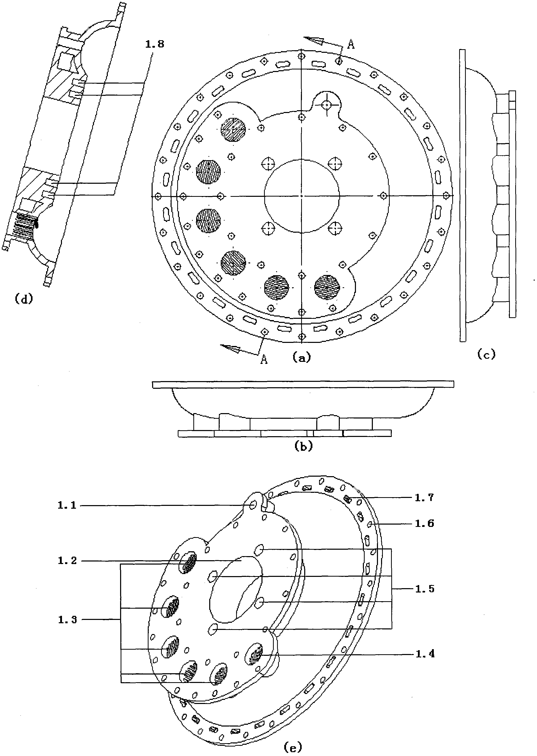
[0085] Figure 1 is a different view of the cylinder head (1). It can be seen from "e figure" that the outermost circular hole on the cylinder head (1) of a is the bolt hole (1.6); there is a circle of rounded arc-shaped holes close to the bolt hole, and these holes are coolant passage holes (1.7) ; There is also a spark plug installation hole (1.1); an exhaust hole (1.4); 5 air intake holes (1.3); 4 circular blind holes for fan wheel shaft installation (1.5); the largest hole in the middle is The a-axis passes through the hole (1.2), and the a-axis (9) bearing or bushing is installed at this position; from "d figure", we can see that there are two circular grooves near the inner wall of the cylinder. The grooves are two sealing ring mounting grooves (1.8). It can be seen from the figure that both the air intake hole (1.3) and the exhaust hole (1.4) are designed in a grid pattern to avoid uneven fric...


PUM


Abstract

The invention relates to a double-rotor rotary piston engine, belonging to internal-combustion engines. A cylinder is of an annular cylinder. A double-rotor mechanism formed by a rotor a and a rotor b rotates in the same direction in a left and right changeable manner in the annular cylinder. The left and right changeable rotate can be converted into continuous rotation and then output through a power output module. Each rotor of the engine comprises a rotor disc and two fan-shaped pistons. The annular cylinder is dynamically divided into four closed spaces through the four pistons. Each rotor rotates in 180 DEG so that four strokes of sucking, compressing, acting and exhausting can be completed. The left and right changeable rotation is realized through a left and right changeable system. Combustible gas is sucked through a normally opened gas inlet. A plurality of gas inlets are arranged on the wall of the annular cylinder. The gas inflow amount can be controlled in real time according to requirements. Waste gas is discharged through a normally opened exhaust hole. Rotation force is directly generated through the regular circle rotor disc. The acting stress point is along the direction of the tangent line of the rotor disc. The double-rotor rotary piston engine is high in power, steady for operation and low in vibration.

Description

technical field [0001] The invention relates to a double-rotor rotary piston engine, which belongs to internal combustion engines. technical background [0002] 1. The traditional four-stroke reciprocating piston engine has relatively mature technology and is currently the mainstream engine. But the reciprocating engine has disadvantages due to its own characteristics. [0003] 1. When the reciprocating piston engine is working, the piston makes a reciprocating linear motion in the cylinder. In order to convert the linear motion of the piston into a rotary motion, a crank-connecting rod mechanism must be used. The smaller the angle between the piston's work direction and the connecting rod, the smaller the effective work. . When the angle between the acting direction of the piston and the connecting rod is 0°, the dead point of acting occurs. Piston work is not very efficiently converted into torque. [0004] 2. The reciprocating piston engine must be equipped with a com...

Claims


Application Information

Patent Timeline
IPC IPC(8): F02B53/02
CPCY02T10/17Y02T10/12
Inventor 王尚锋
Owner 王尚锋
Learn More