Rapid purification sewage treatment device

A sewage treatment device and fast technology, applied in water/sewage treatment, water/sewage multi-stage treatment, water/sludge/sewage treatment, etc., which can solve the problems of inconvenient and rapid treatment of sewage

Inactive Publication Date: 2020-10-20
合肥乡情园林景观设计有限公司
View PDF3 Cites 1 Cited by
  • Summary
  • Abstract
  • Description
  • Claims
  • Application Information

AI Technical Summary

Problems solved by technology

[0009] The purpose of the present invention is to provide a fast purification sewage treatment device to solve the problem that it is not convenient to quickly process sewage in the above-mentioned background technology

Method used


Image

  • Rapid purification sewage treatment device
  • Rapid purification sewage treatment device
  • Rapid purification sewage treatment device

Examples


Embodiment 1

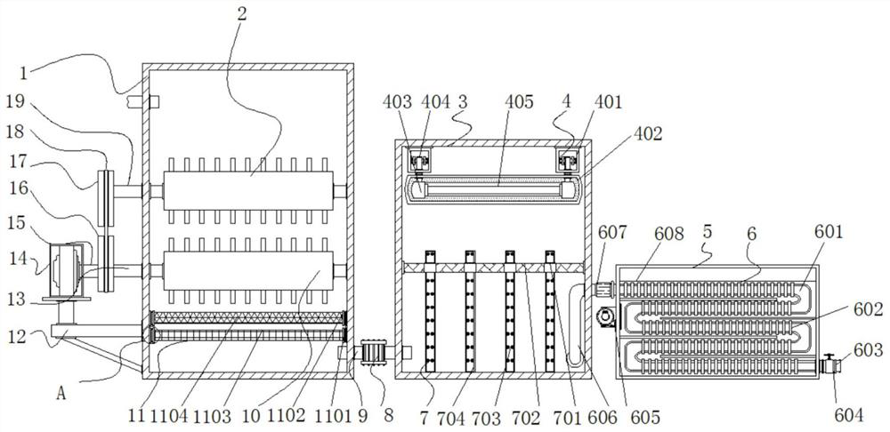
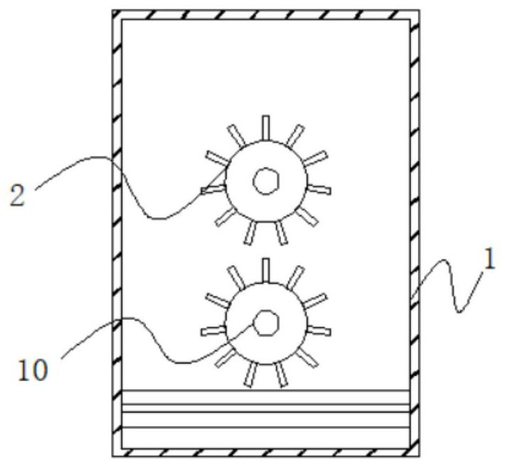
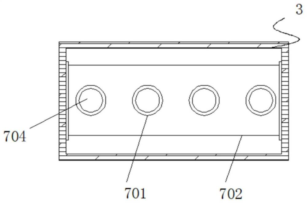
[0035] Example 1: See Figure 1-6 , a rapid purification sewage treatment device, comprising a box body 1, a tank body 3 and a discharge box 5, the bottom end of the box body 1 is provided with a filter structure 11, one side of the box body 1 is provided with a tank body 3, and the box body 1 A through pipe 9 is fixedly connected with the tank body 3, and a second water pump 8 is arranged on one side outside the through pipe 9. The model of the second water pump 8 can be MD-40RM, and one side of the through pipe 9 runs through the The bottom end inside the box body 1, the other side of the through pipe 9 runs through the bottom end inside the tank body 3, the top end inside the tank body 3 is provided with a sterilization mechanism 4, and the bottom end inside the tank body 3 is provided with a purification structure 7 , one side of the tank body 3 is provided with a discharge box 5, and the inside of the discharge box 5 is provided with a waste heat recovery mechanism 6, and...

Embodiment 2

[0038] Embodiment 2: The sterilization and disinfection mechanism 4 is made up of fixed seat 401, mounting seat 402, connecting sleeve block 403, connecting rod 404, ultraviolet sterilizing lamp tube 405, connecting block 406, connecting seat 407 and limit seat 408. Fixedly connected to both sides of the top inside the tank body 3, the inside of the fixed seat 401 is provided with a connecting rod 404, and both sides of the top of the connecting rod 404 are fixedly connected with a connecting block 406, and the width of the connecting block 406 outside is smaller than that of the connecting seat 407. The width of the connecting block 406 is symmetrically distributed with respect to the vertical center line of the connecting rod 404. The bottom end of the connecting rod 404 is fixedly connected with a connecting block 403, and an ultraviolet germicidal lamp tube 405 is arranged between the connecting block 403. The ultraviolet germicidal lamp The model of the tube 405 can be 320...

Embodiment 3

[0040] Embodiment 3: The waste heat recovery mechanism 6 is composed of a conduit 601, a fin 602, an outlet pipe 603, a valve 604, a hot air blower 605, a suction pipe 606, a first water pump 607 and a placement tank 608, which is fixedly connected to the discharge box 5, the inside of the placement groove 608 is provided with a conduit 601, the outside of the conduit 601 is fixedly connected with fins 602, the bottom end of the conduit 601 is fixedly connected with an outlet pipe 603, and one side of the outlet pipe 603 is provided with a valve 604, The top of the conduit 601 runs through the inside of the tank body 3, a first water pump 607 is provided on one side of the top of the suction pipe 606, and the model of the first water pump 607 can be WQ, and the hot air blower 605 is arranged on one side of the placement tank 608 , the model of the hot air blower 605 can be FP-51WA;

[0041] The inner diameter of the placement groove 608 is greater than the outer diameter of th...


PUM


Abstract

The invention discloses a rapid purification sewage treatment device, and specifically relates to the technical field of sewage treatment. The device comprises a box body, a tank body and a dischargebox, a filtering structure is arranged at the bottom end of the interior of the box body; a tank body is arranged on one side of the box body, a through pipe is fixedly connected between the box bodyand the tank body, a second water suction pump is arranged on one side of the exterior of the through pipe, one side of the through pipe penetrates through the bottom end of the interior of the box body, the other side of the through pipe penetrates through the bottom end of the interior of the tank body, and a sterilization and disinfection mechanism is arranged at the top end of the interior ofthe tank body. Through the arrangement of the through groove, the limiting plate, the activated carbon and the connecting plate; during use, when sewage enters the tank body, the sewage passes throughthe connecting plate, the connecting plate is clamped in the through groove formed in the limiting plate, multiple sets of activated carbon are arranged in the connecting plate, peculiar smells in the sewage can be removed through the activated carbon, the sewage discharging quality is improved, and the working efficiency of the device is improved.

Description

technical field [0001] The invention relates to the technical field of sewage treatment, in particular to a rapid purification sewage treatment device. Background technique [0002] With the continuous development of modern society, the discharge of industrial sewage and residential sewage is getting higher and higher. The sewage directly discharged without treatment will pollute the surrounding environmental quality. With the continuous improvement of people's living standards, people The requirements for the surrounding living environment are getting higher and higher. At present, the sewage will be purified when it is discharged. There are still some problems in the existing sewage treatment device. When the sewage is treated, the sewage is easy to settle at the bottom of the box. , It is not convenient for purification treatment, which greatly reduces the effect of sewage treatment. [0003] In the process of realizing the present invention, the inventors have found tha...

Claims


Application Information

Patent Timeline
Patent Type & Authority Applications(China)
IPC IPC(8): C02F9/08
CPCC02F9/00C02F1/001C02F1/283C02F1/325C02F2303/04C02F2303/10C02F2301/08C02F2303/14C02F2303/16
Inventor 沈金凤
Owner 合肥乡情园林景观设计有限公司
Why Eureka
Try Eureka