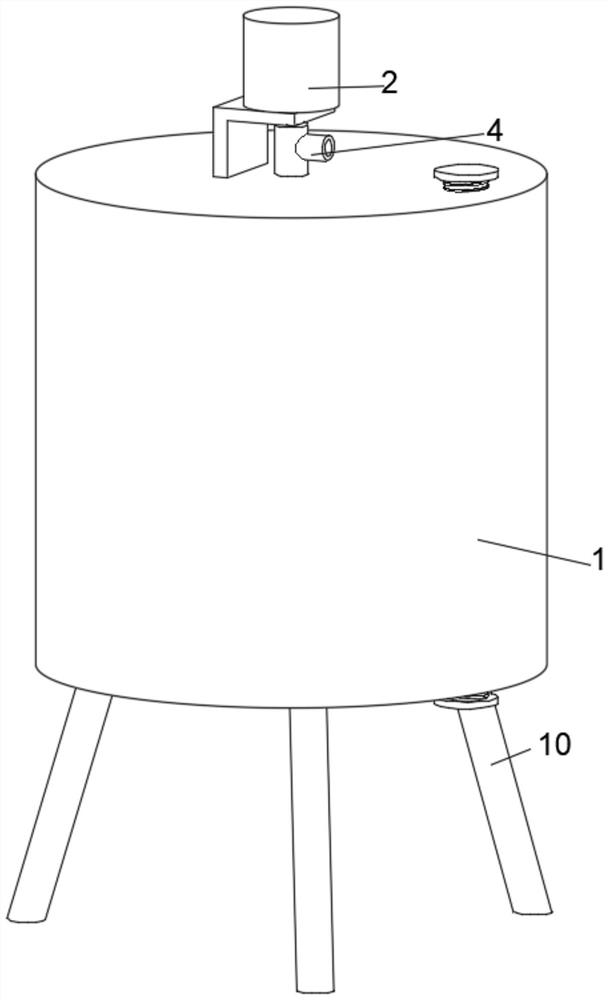
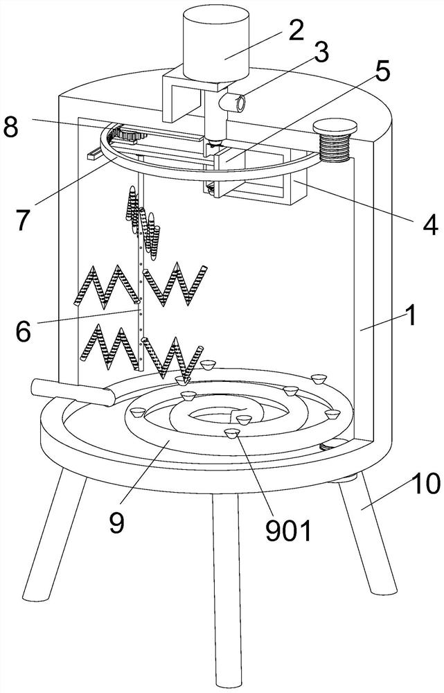
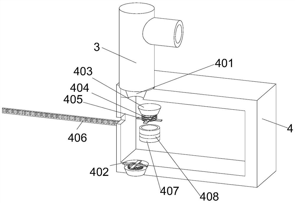
Industrial automatic waste gas purification device

A technology for exhaust gas purification device and industrial automation, which is applied to mixers with rotary stirring devices, chemical instruments and methods, mixers, etc., and can solve the problems of insufficient gas purification, inability to be purified, and entering into the air purifier, etc.

Pending Publication Date: 2021-09-14
宋红瑞
View PDF1 Cites 1 Cited by
  • Summary
  • Abstract
  • Description
  • Claims
  • Application Information

AI Technical Summary

Problems solved by technology

However, this device also has the disadvantage that when the device is in use, the exhaust gas is directly delivered to the box containing the neutralizing agent. Since the gas will form larger bubbles in the neutralizing agent, the bubbles will quickly neutralize The agent floats and explodes, resulting in the exhaust gas in the bubbles not being mixed with the neutralizer. Since the harmful substances in the exhaust gas need to react with the neutralizer to be removed and purified, the unpurified exhaust gas directly enters the air purifier. In the interior, it cannot be purified, resulting in insufficient purification of the discharged gas. In addition, the purified gas needs to be monitored. When the exhaust gas is still not up to standard after purification, it needs to be purified circularly. In view of this, we propose an industrial automation exhaust gas Purification device

Method used


Image

  • Industrial automatic waste gas purification device
  • Industrial automatic waste gas purification device
  • Industrial automatic waste gas purification device

Examples


Embodiment Construction

[0029] In describing the present invention, it should be understood that the terms "center", "longitudinal", "transverse", "length", "width", "thickness", "upper", "lower", "front", " Orientation indicated by rear, left, right, vertical, horizontal, top, bottom, inside, outside, clockwise, counterclockwise, etc. The positional relationship is based on the orientation or positional relationship shown in the drawings, and is only for the convenience of describing the present invention and simplifying the description, rather than indicating or implying that the referred device or element must have a specific orientation, be constructed and operated in a specific orientation, Therefore, it should not be construed as limiting the invention.

[0030] In the description of the present invention, "plurality" means two or more, unless otherwise specifically defined.

[0031] In the description of the present invention, it should be noted that, unless otherwise specified and limited, t...


PUM


Abstract

The invention discloses an industrial automatic waste gas purification device, and belongs to the technical field of industrial waste gas purification. The industrial automatic waste gas purification device comprises a purification box, a motor is fixedly arranged on the top face of the purification box, the lower end of a gas outlet pipe penetrates through the top face of the purification box, extends into the purification box and is connected with a gas exhaust box, and a plurality of supporting legs are welded to the bottom face of the purification box in an annular structure. By means of an exhausting assembly, the motor drives the gas outlet pipe to rotate, so that the gas outlet pipe drives the connected gas exhaust box to rotate; a gear A on a connecting rod connected with the gas exhaust box can be meshed with an annular rack when doing circular motion, so that the gear A rotates, and the gear A can drive an L-shaped rod to doing circular motion; at the moment, a sealing block in an air inlet hole is closed, and a sealing block in an air outlet hole is opened, and purified gas is exhausted through the gas outlet pipe; and by means of the sealing block, the purification time of the gas in the purification box can be prolonged, the gas and a neutralizer are fully purified, and the purification effect of the device is better.

Description

technical field [0001] The invention relates to the technical field of industrial waste gas purification, and more specifically relates to an industrial automatic waste gas purification device. Background technique [0002] The so-called industrial waste gas refers to the general term of all kinds of pollutant gases discharged into the air during the fuel incineration and production process in the enterprise factory area. The principles of industrial waste gas treatment include activated carbon adsorption method, catalytic incineration method, catalytic oxidation method, acid-base neutralization method, plasma method and other principles. Prior art CN109833764A In an industrial automation waste gas purification device, the industrial waste gas is neutralized and purified by setting a neutralization purification pool, so that the waste gas and the neutralization liquid have enough time and space to fully contact, thereby improving the degree of purification of the waste gas a...

Claims


Application Information

Patent Timeline
Patent Type & Authority Applications(China)
IPC IPC(8): B01D53/78B01D53/30B01F3/04B01F7/16B01F7/30B01F15/02B01F15/00
CPCB01D53/78B01D53/30
Inventor 宋红瑞
Owner 宋红瑞
Why Eureka
Try Eureka