Dust falling machine for hydraulic engineering construction site

A water conservancy project, dust machine technology, applied in the use of liquid separation agent, road surface cleaning, separation of dispersed particles, etc., can solve the problems of single function, time-consuming and labor-intensive, and difficult work for staff

Inactive Publication Date: 2020-10-20
李磊
View PDF13 Cites 2 Cited by
  • Summary
  • Abstract
  • Description
  • Claims
  • Application Information

AI Technical Summary

Problems solved by technology

[0004] The purpose of the present invention is to solve the problem that existing dust suppressors often have simple structures and single functions, and often have a small dust suppression range, requiring staff to frequently move to achiev

Method used


Image

  • Dust falling machine for hydraulic engineering construction site
  • Dust falling machine for hydraulic engineering construction site
  • Dust falling machine for hydraulic engineering construction site

Examples


Embodiment 1

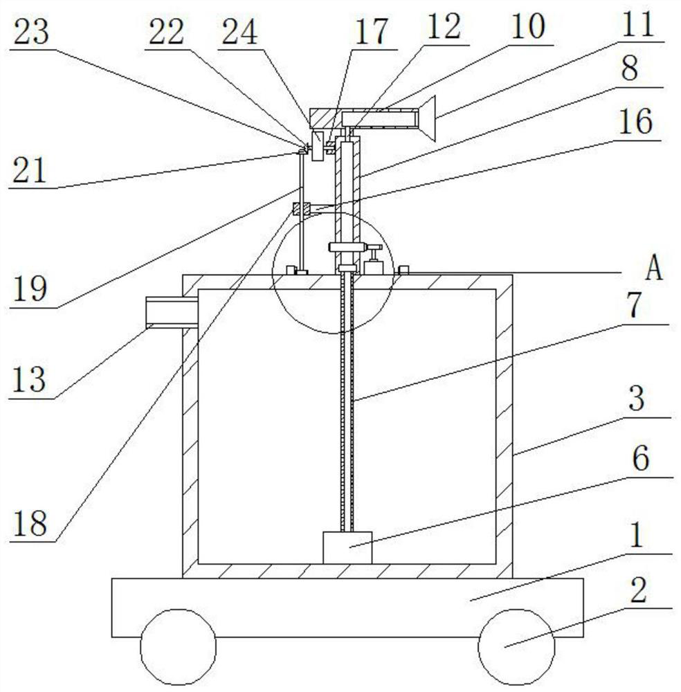
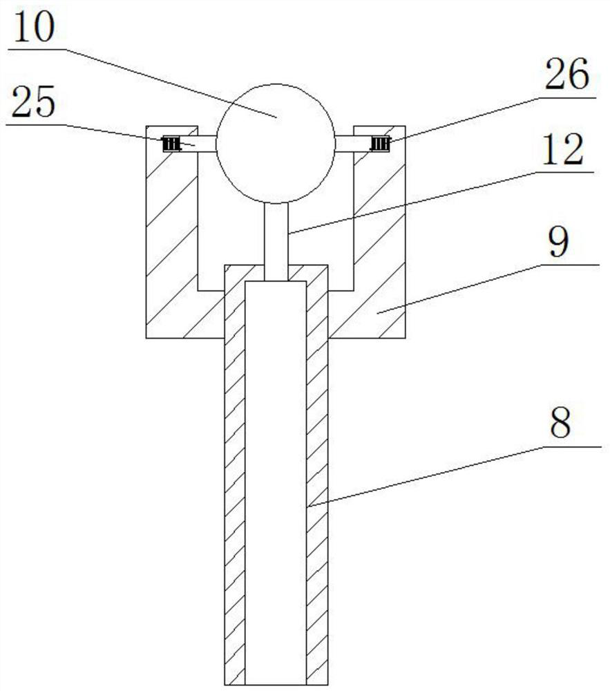
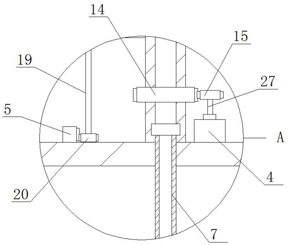
[0021] refer to Figure 1-3 , a water conservancy project construction ground dust suppressor, comprising a base plate 1, four universal wheels 2 are mounted on the bottom of the base plate 1, and the top of the base plate 1 is fixedly connected with a housing 3, and the top of the housing 3 is fixedly installed with a motor 4. The ring gear 5 is fixedly connected to the top of the housing 3, and the water pump 6 is fixedly installed on the inner wall of the bottom of the housing 3. The water outlet of the water pump 6 is connected to one end of the first water pipe 7, and the other end of the first water pipe 7 extends One end of the second water pipe 8 is rotatably sleeved to the outside of the housing 3, one end of two support rods 9 is fixedly connected to the outer side of the second water pipe 8, and the other end of the two support rods 9 is rotatably connected to the same pipe body 10. One end of the pipe body 10 is provided with a nozzle 11, the top of the second wate...

Embodiment 2

[0027] refer to Figure 1-3 , a water conservancy project construction ground dust collector, including a bottom plate 1, four universal wheels 2 are installed on the bottom of the bottom plate 1, and the top of the bottom plate 1 is fixedly connected with a shell 3 by welding, and the top of the shell 3 is connected by bolts The motor 4 is fixedly installed, the top of the housing 3 is fixedly connected with the ring gear 5 by welding, the bottom inner wall of the housing 3 is fixed with a water pump 6 through bolts, and the water outlet of the water pump 6 is connected to one end of the first water pipe 7. The other end of the first water pipe 7 extends to the outside of the housing 3 and is sleeved with one end of the second water pipe 8 . The outer side of the second water pipe 8 is fixedly connected with one end of two support rods 9 by welding. The two support rods 9 The other end of the second water pipe 8 is rotatably connected to the same pipe body 10, one end of the ...


PUM


Abstract

The invention belongs to the technical field of hydraulic engineering, and particularly relates to a dust falling machine for a hydraulic engineering construction site. In allusion to the problems that an existing dust falling machine is usually simple in structure, single in function and small in dust falling range is small, workers need to frequently move to achieve the purpose of large-area dust falling, time and energy are wasted, and difficulty is brought to the work of workers, the invention proposes the following scheme: the dust falling machine comprises a bottom plate, four universalwheels are rotationally mounted at the bottom of the bottom plate, the top of the bottom plate is fixedly connected with a shell, a motor is fixedly mounted at the top of the shell, the top of the shell is fixedly connected with a gear ring, and a water pump is fixedly installed on the bottom inner wall of the shell. By arranging a cam and the motor, the dust falling machine is reasonable in structure and rich in function, the dust falling range is further widened, the purpose of large-area dust falling can be achieved without frequent movement of workers, time and labor are saved, the operation is convenient and fast, and the dust falling machine is practical.

Description

technical field [0001] The invention relates to the technical field of water conservancy engineering, in particular to a ground dust suppressor for water conservancy engineering construction. Background technique [0002] Some new water conservancy projects are newly built on the current rivers, mainly for controlling water flow and utilizing water energy to generate electricity. In the construction of these water conservancy projects, some dust is often brought in, and the dust phenomenon occurs under the blowing of the wind, and The dust will be inhaled by the construction workers along with the air, so the dust needs to be treated, and then it is necessary to use the dust suppressor for the construction site of the water conservancy project to carry out the dust reduction treatment to prevent the occurrence of dust; [0003] However, the existing dust suppressors are often simple in structure, single in function, and often have a small range of dust reduction, requiring s...

Claims


Application Information

Patent Timeline
IPC IPC(8): E01H3/02B01D47/06
CPCB01D47/06E01H3/02
Inventor 李磊
Owner 李磊
Why Eureka
Try Eureka