
Fresh air distribution structure of building air-supply vertical wells

A technology for buildings and fresh air, applied in building structures, building components, buildings, etc., can solve the problems of lower housing prices, low floor area ratio, specific surface area of ​​residential buildings, and high building energy consumption

Pending Publication Date: 2020-10-20
SHANGHAI BOHAN THERMAL ENERGY TECH
View PDF0 Cites 0 Cited by
  • Summary
  • Abstract
  • Description
  • Claims
  • Application Information

AI Technical Summary

Problems solved by technology

Land prices are the driving force behind the high housing prices, but the floor area ratio is a hedging factor for housing prices. A low floor area ratio will further increase housing prices, and a high floor area ratio will lower housing prices.
[0007] The reason why the energy consumption of residential buildings remains high is certainly related to the performance of wall insulation materials and the performance of residential energy equipment such as air conditioners, but the volume ratio and the specific surface area of ​​residential buildings are also hedging factors. High volume ratio and small specific surface area of ​​residential buildings will lead to The surface area of ​​the outer wall shared per unit building area of ​​the residential space is small, the energy exchange intensity with the environment is low, and the building energy consumption is low; on the contrary, the floor area ratio is low and the specific surface area of ​​the residential building is large, the surface area of ​​the outer wall shared evenly per unit building area of ​​the living space is large, High energy exchange intensity with the environment and high building energy consumption
[0008] At present, the volume ratio index of residential buildings and the specific surface area index of residential buildings are constrained by traditional planning regulations and architectural design regulations, which restricts the innovative development of residential buildings

Method used

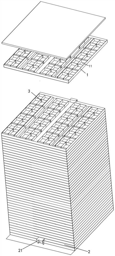

Image

  • Fresh air distribution structure of building air-supply vertical wells
  • Fresh air distribution structure of building air-supply vertical wells
  • Fresh air distribution structure of building air-supply vertical wells

Examples


Embodiment 1

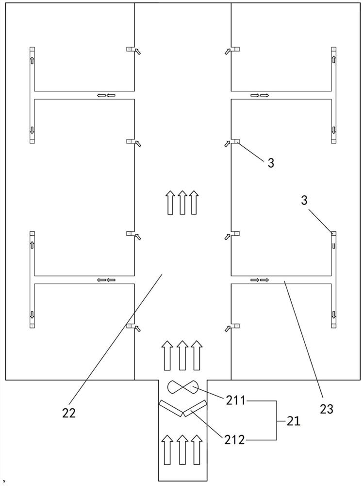
[0052] Please refer to figure 2 , this embodiment adopts integrated distribution of fresh air, that is, at least one total fresh air module 21 delivers fresh air to all air supply shafts 3 at the same time.

[0053] In this embodiment, at least one general air supply port is provided on the outer wall of the fresh air distribution layer 2, and a total fresh air module 21 is arranged on the general air supply port, and the total fresh air module 21 passes through the air supply channel Fresh air can be delivered to several of the air supply shafts 3 .

[0054] In this embodiment, there is no limit to the number of main air supply outlets provided on the outer wall of the fresh air distribution layer 2, which can be set according to the actual volume of the building. As an embodiment, a total air supply port is arranged on the outer wall of the fresh air distribution layer 2, and a total fresh air module 21 is arranged on the air supply port. In this embodiment, this total fre...

Embodiment 2

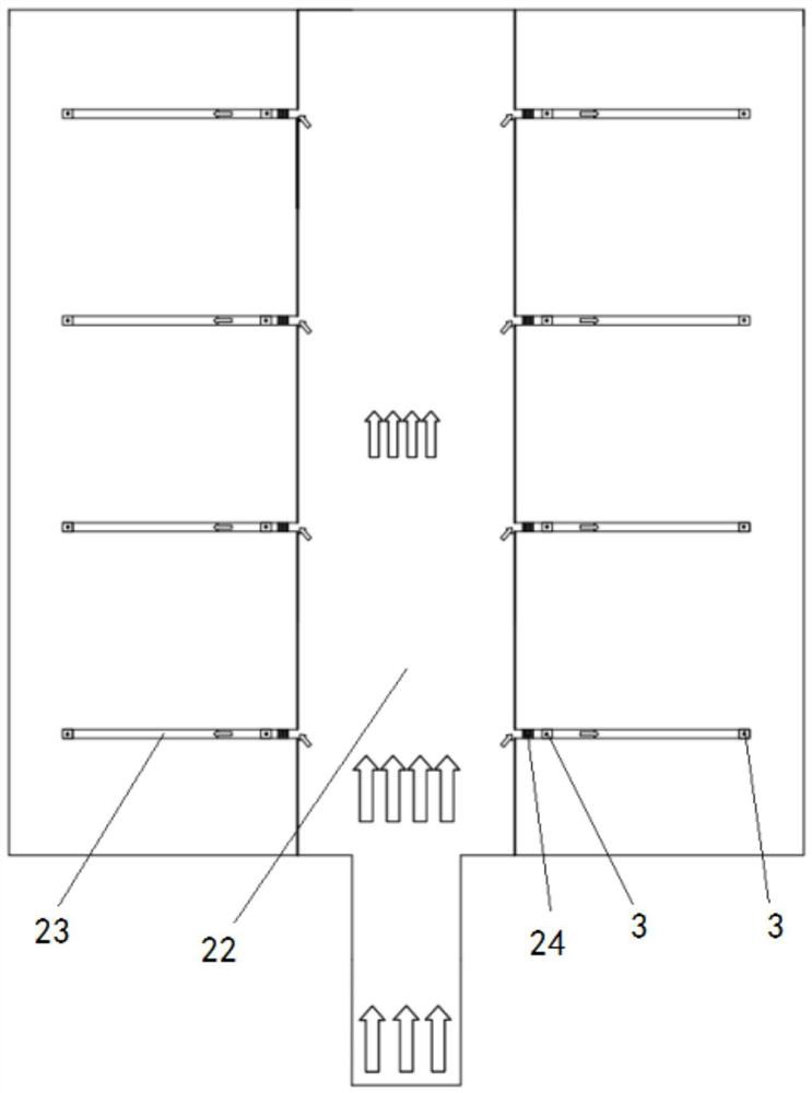
[0060] Please refer to image 3 , this embodiment uses independent distribution of fresh air.

[0061] At least one main air supply port is arranged on the outer wall of the fresh air distribution layer 2;

[0062] The air supply channel includes a main air supply channel 22 and several air supply sub-channels 23, the main air supply channel 22 is horizontally arranged in the fresh air distribution layer 2, and at least one end thereof communicates with the main air supply port;

[0063] Several of the air supply sub-channels 23 are respectively arranged horizontally in the fresh air distribution layer 2 and communicate with the main air supply channel 22;

[0064] The sub-fresh air modules 24 are arranged on several of the air supply sub-channels 23 , and the several of the air supply shafts 3 deliver fresh air through the several of the sub-fresh air modules 24 .

[0065] When some air supply shafts 3 do not need to transport fresh air through the fresh air module (such as...

Embodiment 3

[0073] In this embodiment, the above two fresh air distribution methods are combined, that is, a total fresh air module 21 is set on the main air supply port, and a fresh air distribution module 24 is provided on the air supply sub-channel 23. When it is necessary to deliver fresh air to most of the air supply shafts 3 , then open the total fresh air module 21 and close the branch fresh air module 24;

[0074]As an embodiment, the total fresh air module 21 only provides natural fresh air, that is, it only includes the total fresh air fan 211 and does not include the total fresh air pretreatment module 212. Therefore, the fresh air distribution module 24 includes both the fresh air fan 241 and the fresh air pretreatment module 241 The processing module 242, on the same air supply channel 23, distributes the fresh air module 24 and the air supply shaft 3 sequentially along the flow direction of the fresh air. The place where the wind blows first is the front, and the place where ...


PUM


Abstract

The invention relates to a fresh air distribution structure of building air-supply vertical wells. A building comprises a fresh air distribution layer, a plurality of flat layers and a plurality of air-supply vertical wells; the plurality of air-supply vertical wells communicate with the fresh air distribution layer and the plurality of flat layers correspondingly; an air-supply channel is disposed in the fresh air distribution layer; and at least one main fresh air module or / and a plurality of auxiliary fresh air modules communicate with the plurality of air-supply vertical wells correspondingly through the air-supply channel, and fresh air on the outside can be delivered into the plurality of air-supply vertical wells. Accordingly, the fresh air distribution structure can effectively distribute fresh air to the air-supply vertical wells.

Description

technical field [0001] The invention relates to the technical field of ventilation in buildings, in particular to a fresh air distribution structure for an air supply shaft of a building. Background technique [0002] Under traditional building design codes, the structural design of buildings must meet the rigid constraints of natural ventilation and lighting indicators. [0003] To make buildings meet the restrictive requirements for natural lighting and ventilation, designers must adopt technical measures such as separating multiple buildings, thinning the thickness of a single building, and setting structural joints for lighting and ventilation in each building, so as to realize the north-south transparency of the building. , to realize the kitchen and bathroom windows to the outside, to ensure sufficient natural lighting and ventilation. [0004] However, the adoption of technical measures such as separating multiple buildings, thinning the thickness of a single buildin...

Claims


Application Information

Patent Timeline
IPC IPC(8): E04F17/04F24F5/00F24F7/06F24F13/02F24F13/28
CPCE04F17/04F24F5/00F24F7/065F24F13/0227F24F13/28
Inventor 薛世山吴飞飞李成伟韦林林应小勇刘帅帅马骥王庆伦
Owner SHANGHAI BOHAN THERMAL ENERGY TECH
Learn More