
Oil well overground security device for oil exploitation

A technology for oil exploitation and oil wells, which is applied in the field of oil well ground security devices for oil exploitation, and can solve the problems of oil waste, injury, local environmental pollution, etc.

Inactive Publication Date: 2020-10-20
韦贵升
View PDF0 Cites 0 Cited by
  • Summary
  • Abstract
  • Description
  • Claims
  • Application Information

AI Technical Summary

Problems solved by technology

[0003] The existing oil extraction device is located on the ground with an oil well. If there is an oil eruption during the extraction process, the oil will be sprayed to the ground through the oil well, which will not only cause a large amount of waste of oil, but also cause local environmental pollution. The impulsive force carried by the oil well is relatively large. If there are workers near the oil well, it will cause greater damage to them. Therefore, it is necessary to install a safety device outside the oil well.

Method used


Image

  • Oil well overground security device for oil exploitation
  • Oil well overground security device for oil exploitation
  • Oil well overground security device for oil exploitation

Examples


Embodiment 1

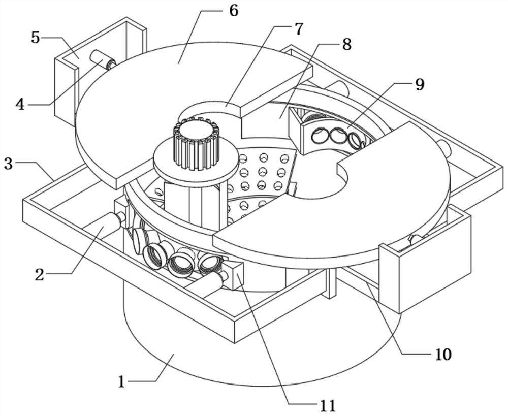
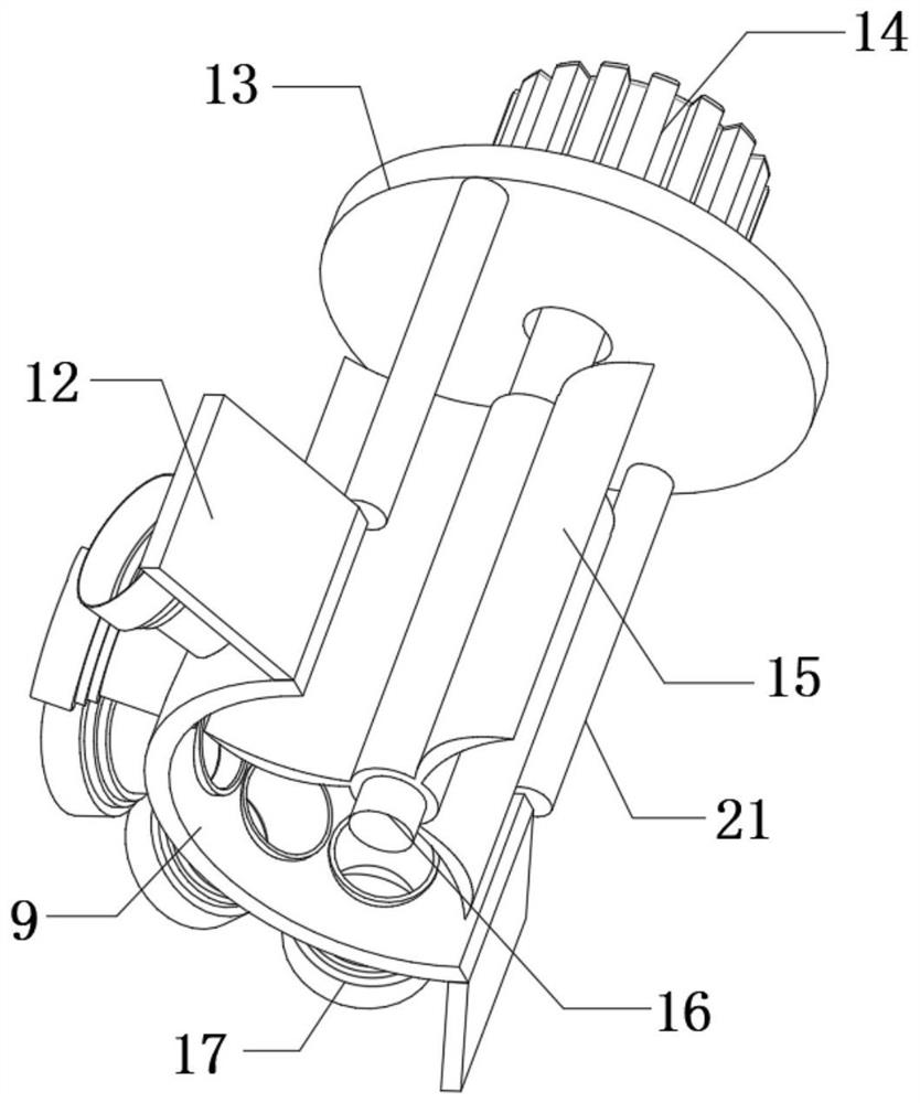
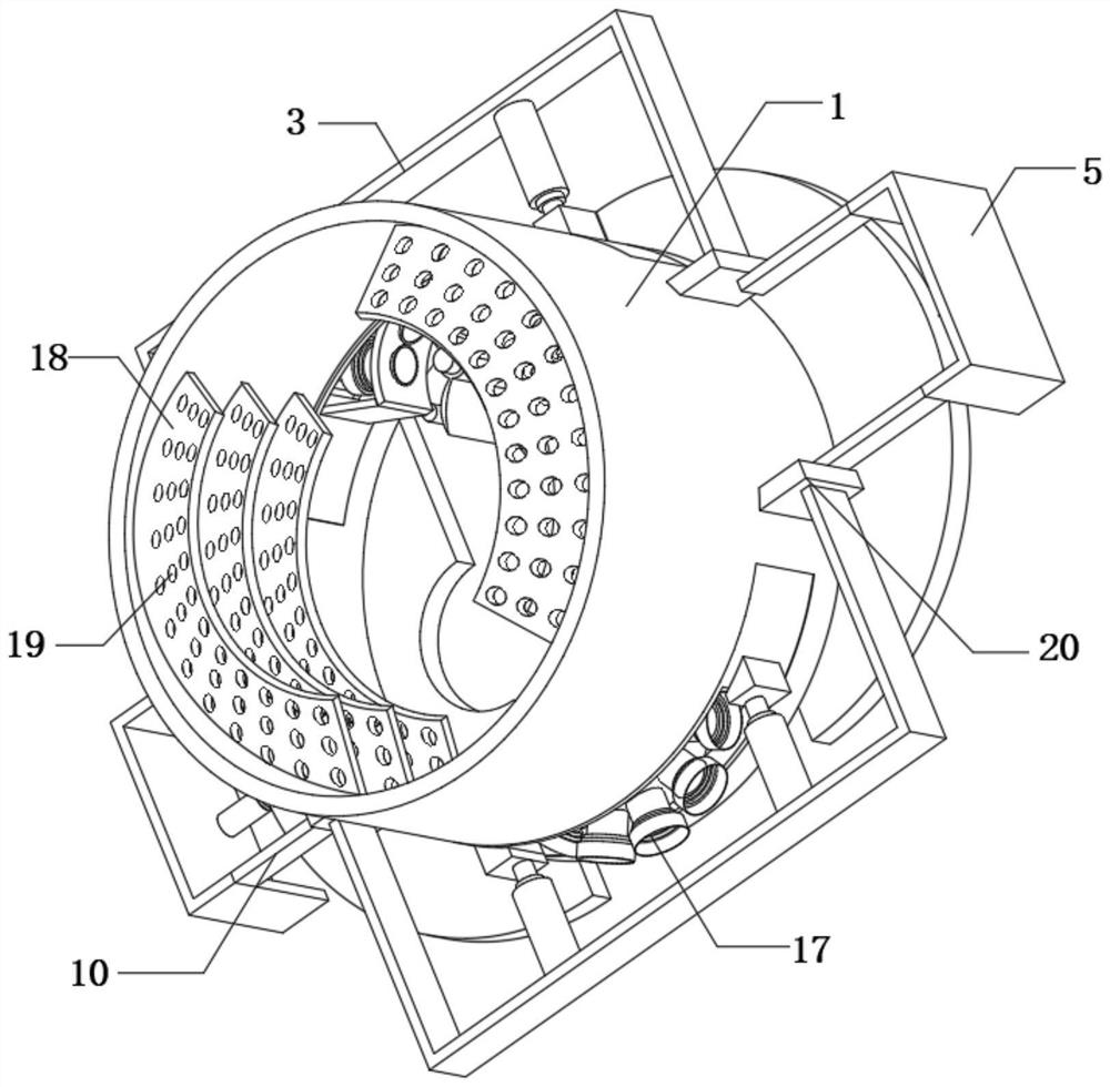
[0029] refer to Figure 1-4 , an oil well ground security device for oil development, comprising a protective frame 1, the outer wall of the protective frame 1 is fixedly connected with four connecting plates 20, and the outer walls of the opposite sides of each adjacent two connecting plates 20 are fixedly connected with a fixed Rod 10, the outer walls of every two adjacent fixed rods 10 are fixedly connected with the same connecting frame 5, and the outer walls of the opposite side of the two connecting frames 5 are fixedly connected with No. 2 hydraulic cylinder 4, and the two No. 2 hydraulic cylinders 4 is connected with a synchronous hydraulic system, and the other ends of the two No. 2 hydraulic cylinders 4 are fixedly connected with interceptor plates 6 , and the top outer walls of the joints of the two interceptor plates 6 are provided with through holes 7 .

[0030] In the present invention, the outer wall of the protective frame 1 is provided with two connecting hole...

Embodiment 2

[0039] refer to Figure 5-6 , an oil well ground security device for oil development, comprising a protective frame 1, the outer wall of the protective frame 1 is fixedly connected with four connecting plates 20, and the outer walls of the opposite sides of each adjacent two connecting plates 20 are fixedly connected with a fixed Rod 10, the outer walls of every two adjacent fixed rods 10 are fixedly connected with the same connecting frame 5, and the outer walls of the opposite side of the two connecting frames 5 are fixedly connected with No. 2 hydraulic cylinder 4, and the two No. 2 hydraulic cylinders 4 is connected with a synchronous hydraulic system, and the other ends of the two No. 2 hydraulic cylinders 4 are fixedly connected with interceptor plates 6 , and the top outer walls of the joints of the two interceptor plates 6 are provided with through holes 7 .

[0040] In the present invention, the outer wall of the protective frame 1 is provided with two connecting hole...


PUM


Abstract

The invention belongs to the technical field of oil exploitation, and particularly relates to an oil well overground security device for oil exploitation. According to an existing oil exploitation device, an oil well is placed on the ground, in the exploitation process, if oil blows out, oil is sprayed to the ground through the oil well, a large amount of oil is wasted, and local environmental contamination is caused. According to the technical scheme, the oil well overground security device comprises a protective frame, four connecting plates are fixedly connected to the outer wall of the protective frame, the outer walls of the opposite sides of the every two adjacent connecting plates are each fixedly connected with a fixing rod, and the outer walls of every two adjacent fixing rods arefixedly connected with the same connecting frame. By arranging the protective frame, a second hydraulic cylinder and a stop plate, when the security device is installed, the protective frame is installed at the outer side of the oil well, when the oil well blows out, the second hydraulic cylinder is adjusted to drive the stop plate to stop sprayed oil, and therefore the security effect is achieved.

Description

technical field [0001] The invention relates to the technical field of petroleum exploitation, in particular to an aboveground security device for oil wells used in petroleum exploitation. Background technique [0002] Oil extraction refers to the behavior of digging and extracting oil in places where oil is stored; in the process of oil extraction, oil and gas flow from the reservoir to the bottom of the well, and then rise from the bottom of the well to the wellhead. [0003] The existing oil extraction device is located on the ground with an oil well. If there is an oil eruption during the extraction process, the oil will be sprayed to the ground through the oil well, which will not only cause a large amount of waste of oil, but also cause local environmental pollution. The impulsive force carried by the oil well is relatively large. If there are workers near the oil well, it will cause greater damage to them. Therefore, it is necessary to install a security device outsid...

Claims


Application Information

Patent Timeline
Patent Type & Authority Applications(China)
IPC IPC(8): E21B33/06E21B33/08
CPCE21B33/06E21B33/08
Inventor 韦贵升
Owner 韦贵升
Learn More