
Hydraulic oil box and engineering machine with hydraulic oil box

A technology for hydraulic oil tanks and oil tanks, which is applied to mechanical equipment, oil supply tank devices, earth movers/shovels, etc., and can solve problems such as limited ability to eliminate air bubbles and short residence time

Inactive Publication Date: 2020-10-20
ZOOMLION HEAVY IND CO LTD
View PDF6 Cites 0 Cited by
  • Summary
  • Abstract
  • Description
  • Claims
  • Application Information

AI Technical Summary

Problems solved by technology

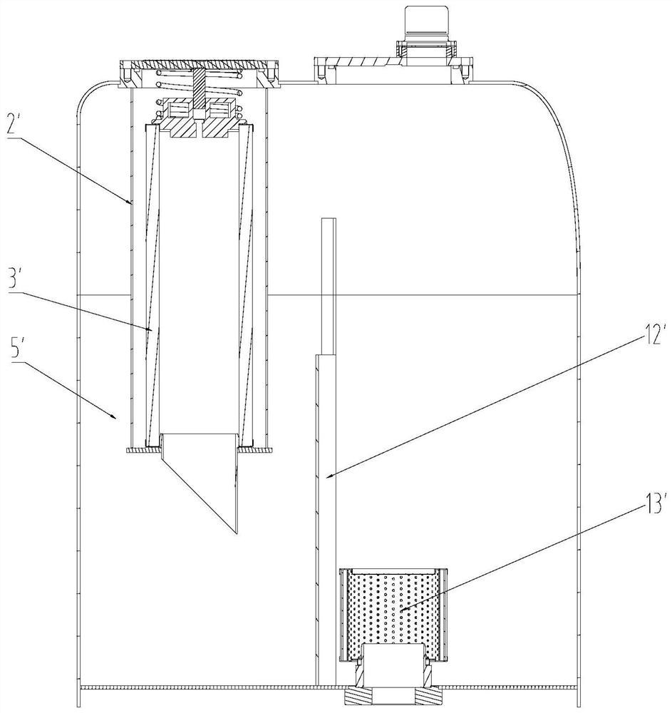
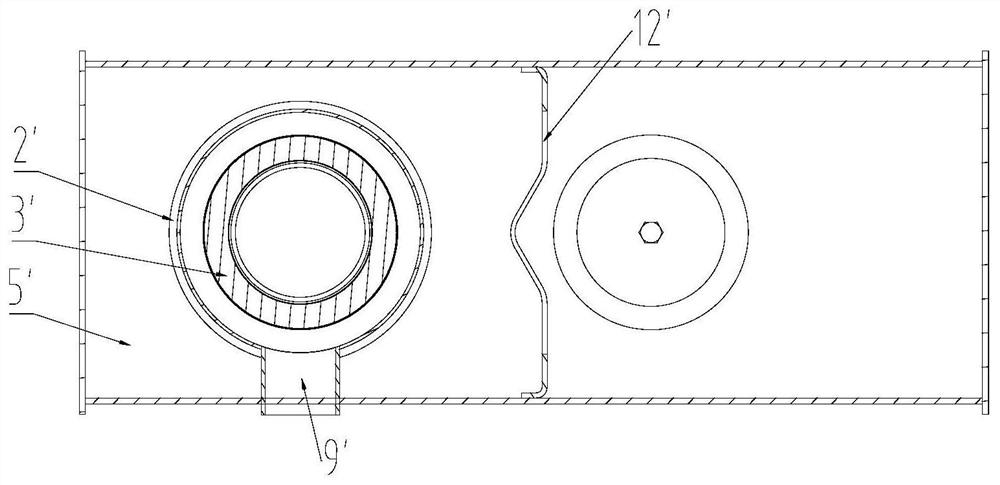
[0004] figure 1 and figure 2 The problem with the hydraulic oil tank shown is that the hydraulic oil will be mixed with a large amount of oil and gas after the hydraulic system circulates. Since the sealed oil return box shell 2' and the oil return filter element 3' have almost no air bubble elimination ability, most The air bubbles will be directly discharged from the oil return box to the tank cavity 5', and due to the small design of the tank and the high viscosity of the hydraulic oil, the residence time of the hydraulic oil in the tank cavity 5' is short, so only the additional partition 12' is used The way to increase the disturbance and residence time of oil and gas in the tank cavity 5' is to remove the air bubbles mixed in the hydraulic oil, and the ability to eliminate air bubbles is very limited

Method used


Image

  • Hydraulic oil box and engineering machine with hydraulic oil box
  • Hydraulic oil box and engineering machine with hydraulic oil box
  • Hydraulic oil box and engineering machine with hydraulic oil box

Examples


Embodiment Construction

[0028] It should be noted that, in the case of no conflict, the embodiments and features in the embodiments of the present invention can be combined with each other.

[0029] In the present invention, it should be understood that the orientation or positional relationship indicated by the terms "deviation", "facing" and the like correspond to the actual orientation or positional relationship; inside and outside. These are only for the convenience of describing the present invention and simplifying the description, rather than indicating that the referred device or element must have a specific orientation, be constructed and operated in a specific orientation, and thus should not be construed as limiting the present invention.

[0030] In the present invention, unless otherwise clearly specified and limited, terms such as "installation", "connection", "connection" and "fixation" should be understood in a broad sense, for example, it can be a fixed connection or a detachable con...


PUM


Abstract

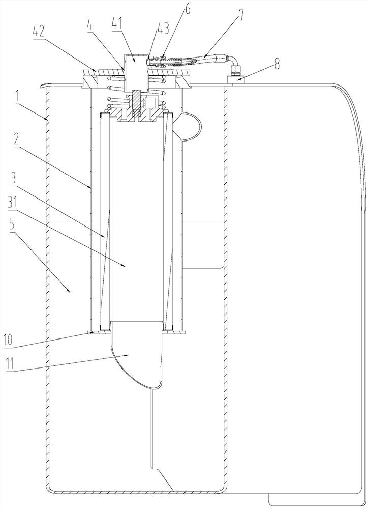
The invention relates to the field of hydraulic devices, and discloses a hydraulic oil box and an engineering machine. The hydraulic oil box comprises an oil box shell and an oil return case. An oil box cavity is formed in the oil box shell, and an oil return opening is arranged at the top. The oil return case comprises a top cover, an oil return case shell, an oil return filter element and an oilreturn pipe. The top cover is arranged at the oil return opening. The oil return case shell extends into the oil box cavity from the bottom of the top cover. The oil return filter element is mountedin the oil return case shell and is arranged to allow hydraulic oil in the oil return case shell to enter the oil box cavity through the oil return filter element. The top cover is provided with an exhaust pipeline, the gas inlet end of the exhaust pipeline communicates into the oil return case shell, and the gas outlet end of the exhaust pipeline communicates to the outer portion of the oil box shell. The oil return case shell comprises a barrel segment at least located on the upper portion, an oil return port is formed on the side wall of the barrel segment, an outlet of the oil return pipecommunicates with the oil return port, and the oil return pipe tangentially extends relative to the barrel segment from the oil return port.

Description

technical field [0001] The invention relates to the field of hydraulic devices, in particular to a hydraulic oil tank and engineering machinery with the hydraulic oil tank. Background technique [0002] During the storage, transportation and use of hydraulic oil, air will inevitably be mixed in, and air usually appears in the hydraulic oil in the form of air bubbles. For the oil tank of an open hydraulic system, under normal circumstances, its upper part is connected with the air, and the lower part stores hydraulic oil. Due to the miniaturized design of the oil tank and the viscosity of the hydraulic oil, the residence time of the hydraulic oil in the oil tank is short, and the air bubbles float to the upper part. The speed is slow, and the ability to eliminate air bubbles in the hydraulic oil is extremely low. The air bubbles mixed in the hydraulic oil will not only reduce the bulk modulus of the oil, increase the compressibility of the oil, and then cause the action erro...

Claims


Application Information

Patent Timeline
IPC IPC(8): F15B21/044F15B21/041F15B1/26E02F9/08
CPCE02F9/0883F15B1/26F15B21/041F15B21/044
Inventor 杜贞棉刘象宝余振华田永丰
Owner ZOOMLION HEAVY IND CO LTD
Learn More