A joint calibration method for laser radar and millimeter wave radar

A millimeter wave radar and lidar technology, applied in radio wave measurement systems, instruments, etc., can solve problems such as being unsuitable for large-scale deployment or mass production, reducing calibration efficiency, and unstable effects, achieving automatic high-precision calibration, Improve the calibration efficiency and eliminate the effect of human factor interference

Active Publication Date: 2020-11-24
AUTOCORE INTELLIGENT TECH NANJING CO LTD
View PDF8 Cites 1 Cited by
  • Summary
  • Abstract
  • Description
  • Claims
  • Application Information

AI Technical Summary

Problems solved by technology

This method has low calibration accuracy and unstable results, which greatly reduces the calibration efficiency and is not suitable for large-scale deployment or mass production

Method used


Image

  • A joint calibration method for laser radar and millimeter wave radar
  • A joint calibration method for laser radar and millimeter wave radar
  • A joint calibration method for laser radar and millimeter wave radar

Examples


Embodiment

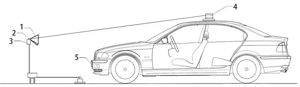
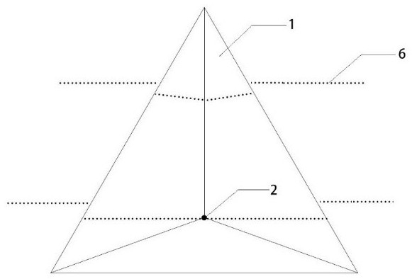
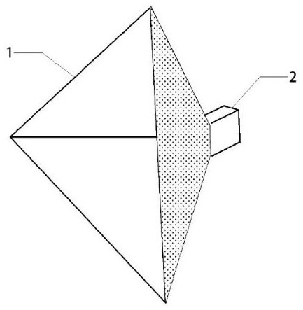
[0021] In this example, if Figure 1-3 As shown, the laser radar 4 and the millimeter-wave radar 5 are fixedly installed at predetermined positions of the electric vehicle, and the relative position between them is fixed, and a corner reflector 1 that can move vertically in space is installed within the sensing range of the millimeter-wave radar 5 , the photosensitive unit 2 for receiving the infrared light 6 emitted by the laser radar 5 is installed at the apex of the corner reflector 1 .

[0022] Among them, the corner reflector 1 can form a strong reflection point within the sensing range of the 24GHz or 77GHz millimeter-wave radar. The corner reflector specification needs to be greater than 0db and less than 20db, and it is best to use a 10db corner reflector. The photosensitive unit 2 can receive the infrared light 6 emitted by the laser radar 4 , such as 905nm or 1550nm. The photosensitive unit can be a point photosensitive unit, a line photosensitive unit or an area ph...


PUM


Abstract

The invention relates to a joint calibration method of laser radar and millimeter wave radar, comprising the following steps: setting a corner reflector that can move in the vertical direction in the common perception area of ​​the millimeter wave radar and laser radar; the output of the laser radar According to the point cloud information of the corresponding wire harness, according to the front and back spatial position relationship of the corner reflector, the spatial coordinates of the corners of the corner reflector in the laser radar coordinate system are obtained, and according to the original point cloud information output by the millimeter wave radar, it is obtained The spatial coordinates of the apex of the corner reflector in the millimeter-wave radar coordinate system; moving the corner reflector to obtain multiple sets of calibration data of the corner reflector at different positions; finding the laser radar coordinates according to the calibration data system and the corresponding relationship between the millimeter-wave radar coordinate system. The invention can perform automatic calibration, eliminates the interference of human factors, improves the calibration efficiency, and can meet the requirements of large-scale deployment or mass production.

Description

technical field [0001] The invention relates to a joint calibration method of laser radar and millimeter wave radar, belonging to the technical field of automatic driving. Background technique [0002] At present, self-driving vehicles generally use a variety of sensors for object perception and positioning, among which lidar and millimeter-wave radar are the most commonly used sensors. In a multi-sensor detection system, there must be a unified coordinate system. Therefore, before using millimeter-wave radar and lidar for sensor fusion, joint spatial calibration of the two sensors must be performed to ensure that the data obtained by the two sensors have a unified coordinate system. The reference standard can be converted to each other, but there is no mature joint calibration method to calibrate the two sensors with high precision. [0003] Due to the large differences in the characteristics of lidar and millimeter-wave radar, it is difficult to develop an automatic calib...

Claims


Application Information

Patent Timeline
Patent Type & Authority Patents(China)
IPC IPC(8): G01S7/40G01S7/497
CPCG01S7/40G01S7/497
Inventor 刘慧远刘心刚张旸陈诚刘洁
Owner AUTOCORE INTELLIGENT TECH NANJING CO LTD
Why Eureka
Try Eureka