
Method and system for detecting defects of power transmission line equipment

A technology for transmission lines and primary equipment, applied in the field of detection of transmission line equipment defects, can solve the problems of difficult extraction and distinction of feature points, high rate of false alarms in defect recognition, and difficulty in using deep learning network theoretical detection accuracy due to the amount of data.

Pending Publication Date: 2020-10-20
CHINA ELECTRIC POWER RES INST +2
View PDF0 Cites 15 Cited by
  • Summary
  • Abstract
  • Description
  • Claims
  • Application Information

AI Technical Summary

Problems solved by technology

At present, most inspection images in the industry rely on manual interpretation to find defects, which limits the further improvement of inspection efficiency
[0003] The background texture of the power equipment is complex, which makes it difficult to extract and distinguish the feature points of the power equipment, which affects the recognition effect
The normal equipment on the transmission line accounts for the vast majority, resulting in a high rate of false alarms in defect identification
At present, the recognition effect of mainstream deep learning network models cannot meet the requirements of industry applications
[0004] Traditional image recognition technology judges equipment defects through artificially designed matching templates, functions and other indicators, and cannot improve the recognition effect through incremental data
The recognition effect of the deep learning model can be improved with the expansion of the number of training sets. However, at present, manual labeling inspection image data is subject to the dual constraints of cost and efficiency, and the amount of data is difficult to achieve the theoretical detection accuracy of the existing deep learning network.

Method used


Image

  • Method and system for detecting defects of power transmission line equipment
  • Method and system for detecting defects of power transmission line equipment
  • Method and system for detecting defects of power transmission line equipment

Examples


Embodiment Construction

[0033] Exemplary embodiments of the present invention will now be described with reference to the drawings; however, the present invention may be embodied in many different forms and are not limited to the embodiments described herein, which are provided for the purpose of exhaustively and completely disclosing the present invention. invention and fully convey the scope of the invention to those skilled in the art. The terms used in the exemplary embodiments shown in the drawings do not limit the present invention. In the figures, the same units / elements are given the same reference numerals.

[0034] Unless otherwise specified, the terms (including scientific and technical terms) used herein have the commonly understood meanings to those skilled in the art. In addition, it can be understood that terms defined by commonly used dictionaries should be understood to have consistent meanings in the context of their related fields, and should not be understood as idealized or over...


PUM


Abstract

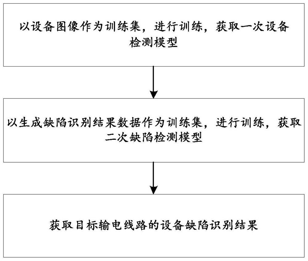
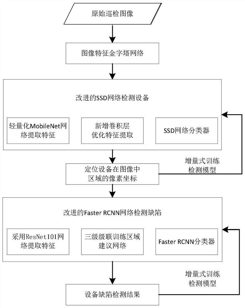
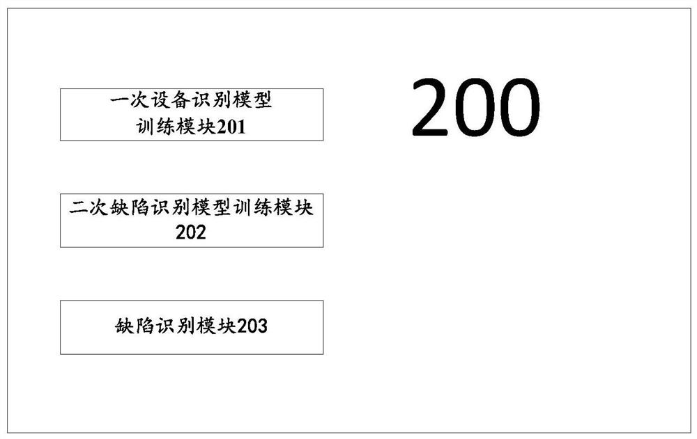
The invention discloses a method and system for detecting defects of power transmission line equipment, and belongs to the technical field of power transmission line inspection. The method comprises:training by taking an equipment image as a training set to obtain a primary defect detection model; taking the generated defect recognition result data as a training set, and performing training to obtain a secondary defect detection model; and obtaining an inspection image of the target power transmission line as input data, inputting the inspection image into the primary defect detection model,obtaining an equipment image of the target power transmission line, taking the equipment image of the target power transmission line as secondary input data, inputting the secondary input data into the secondary defect detection model, and obtaining an equipment defect identification result of the target power transmission line. A two-stage detection and incremental detection model training mode is adopted, so that the defect recognition accuracy can be improved.

Description

technical field [0001] The present invention relates to the technical field of power transmission line inspection, and more specifically, to a method and system for detecting defects of power transmission line equipment. Background technique [0002] In recent years, unmanned aerial vehicles (UAVs) have been widely used in power inspections. They can collect images of transmission line equipment from multiple angles at short distances, which greatly improves the inspection efficiency compared with traditional manual inspections. At present, most inspection images in the industry rely on manual interpretation to find defects, which limits the further improvement of inspection efficiency. [0003] The background texture of the power equipment is complex, which makes it difficult to extract and distinguish the feature points of the power equipment, which affects the recognition effect. The normal equipment on the transmission line accounts for the vast majority, resulting in a...

Claims


Application Information

Patent Timeline
IPC IPC(8): G06K9/62G06K9/46G06N3/04G06N3/08G07C1/20G01N21/88
CPCG06N3/08G07C1/20G01N21/8851G01N2021/8854G01N2021/8887G01N2021/888G06V10/40G06N3/045G06F18/241G06F18/214
Inventor 谈家英蔡焕青李程启邵瑰玮付晶刘壮周立玮文志科胡霁陈怡曾云飞姚金霞周超
Owner CHINA ELECTRIC POWER RES INST
Learn More