Bonding structure, manufacturing method thereof and display panel

A manufacturing method and bonding technology, applied in semiconductor/solid-state device manufacturing, electrical components, electrical solid-state devices, etc., can solve the problems of affecting the conductive effect, small quantity, and high contact area requirements

Inactive Publication Date: 2020-10-20
BAZHOU YUNGU ELECTRONICS TECH CO LTD
View PDF23 Cites 0 Cited by
  • Summary
  • Abstract
  • Description
  • Claims
  • Application Information

AI Technical Summary

Problems solved by technology

However, the anisotropic conductive adhesive has high requirements on the contact area between the pad and the pad. When the c

Method used


Image

  • Bonding structure, manufacturing method thereof and display panel
  • Bonding structure, manufacturing method thereof and display panel
  • Bonding structure, manufacturing method thereof and display panel

Examples


Embodiment Construction

[0024] In order to make the above objects, features and advantages of the present invention more comprehensible, specific implementations of the present invention will be described in detail below in conjunction with the accompanying drawings. In the following description, numerous specific details are set forth in order to provide a thorough understanding of the present invention. However, the present invention can be implemented in many other ways different from those described here, and those skilled in the art can make similar improvements without departing from the connotation of the present invention, so the present invention is not limited by the specific embodiments disclosed below.

[0025] In describing the present invention, it is to be understood that the terms "center", "longitudinal", "transverse", "length", "width", "thickness", "upper", "lower", "front", " Back", "Left", "Right", "Vertical", "Horizontal", "Top", "Bottom", "Inner", "Outer", "Clockwise", "Counter...


PUM


Abstract

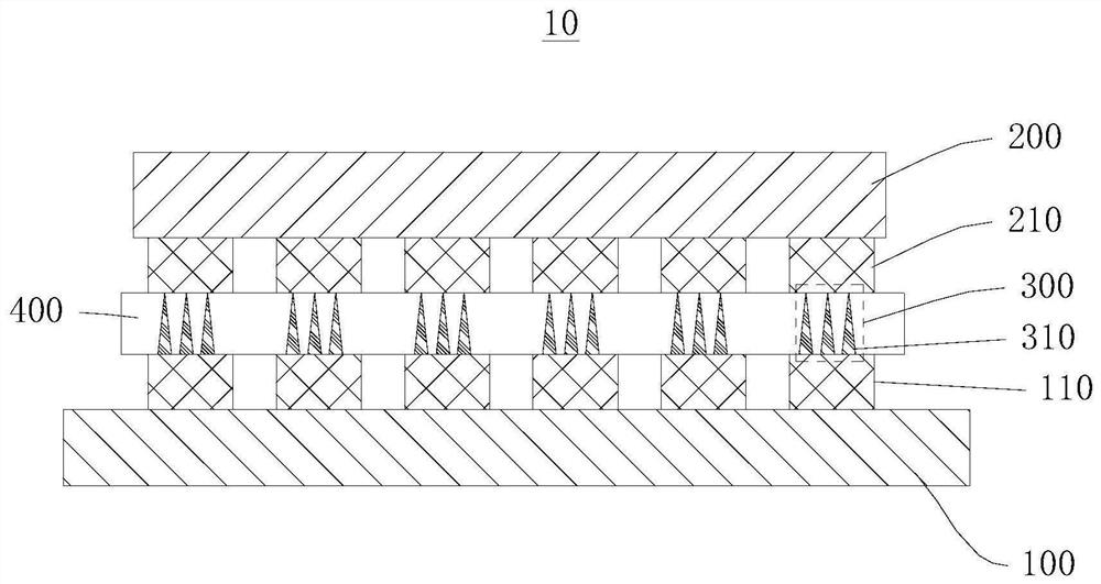
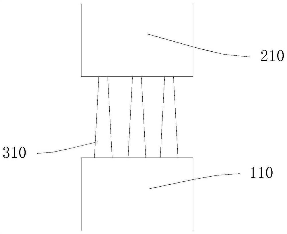
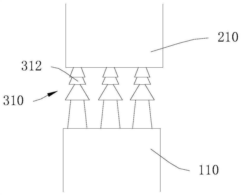
The invention relates to a bonding structure, a manufacturing method thereof and a display panel. The bonding structure comprises a first device, a second device and a conductive column array. The first device includes a first electrode. And the second device and the first device are arranged oppositely. The second device includes a second electrode. And the conductive column array is clamped between the first electrode and the second electrode to electrically connect the first electrode and the second electrode. The two ends of the conductive column array can be in contact connection with thefirst electrode and the second electrode respectively, so that good electric contact between the first electrode and the second electrode can be ensured by setting the contact areas between the two ends of the conductive column array and the first electrode and between the two ends of the conductive column array and the second electrode. The two ends of the conductive column array are respectively in contact with the first electrode and the second electrode, so that the purpose of circuit conduction can be achieved.

Description

technical field [0001] The invention relates to the field of display technology, in particular to a bonding structure, a manufacturing method thereof, and a display panel. Background technique [0002] With the development of display technology, the requirements for electrical connections between panels and components are getting higher and higher. [0003] In the traditional technology, the electrical connection between the pads of the panel and the pads of components is realized through the metal particles exposed in the anisotropic conductive glue (ACF) after the particles are crushed. However, the anisotropic conductive adhesive has high requirements on the contact area between the pad and the pad. When the contact area is small, the number of metal particles between the pad and the pad is small, which affects the conductive effect. Contents of the invention [0004] Based on this, it is necessary to provide a bonding structure, a manufacturing method thereof, and a d...

Claims


Application Information

Patent Timeline
IPC IPC(8): H01L23/488H01L21/60H01L27/32
CPCH01L24/13H01L24/11H01L24/81H01L2224/111H01L2224/13018H01L2224/13023H01L2224/812H10K59/123
Inventor 朱永斌
Owner BAZHOU YUNGU ELECTRONICS TECH CO LTD
Why Eureka
Try Eureka