Self-excitation single-phase generator

A single-phase generator, self-excited technology, applied in synchronous generators, synchronous motors with static armatures and rotating magnets, magnetic circuits, etc. stability issues

Active Publication Date: 2020-10-20
安徽德科电气科技有限公司
View PDF13 Cites 0 Cited by
  • Summary
  • Abstract
  • Description
  • Claims
  • Application Information

AI Technical Summary

Problems solved by technology

[0003] The current self-excited single-phase generator rotor has permanent magnets embedded between the front and rear claw poles to increase the magnetic conductivity of the claw poles, but the position of the permanent magnets is unstable and directly affects the performance of the product, which increases the difficulty of assembly

Method used


Image

  • Self-excitation single-phase generator
  • Self-excitation single-phase generator
  • Self-excitation single-phase generator

Examples


Embodiment Construction

[0018] The present invention will be further described in detail below in conjunction with the accompanying drawings and specific embodiments. The embodiments of the present invention have been presented for purposes of illustration and description, but are not intended to be exhaustive or to limit the invention to the form disclosed. Many modifications and changes will be apparent to those of ordinary skill in the art. The embodiment was chosen and described in order to better explain the principles of the invention and the practical application, and to enable others of ordinary skill in the art to understand the invention and design various embodiments with various modifications as are suited to the particular use.

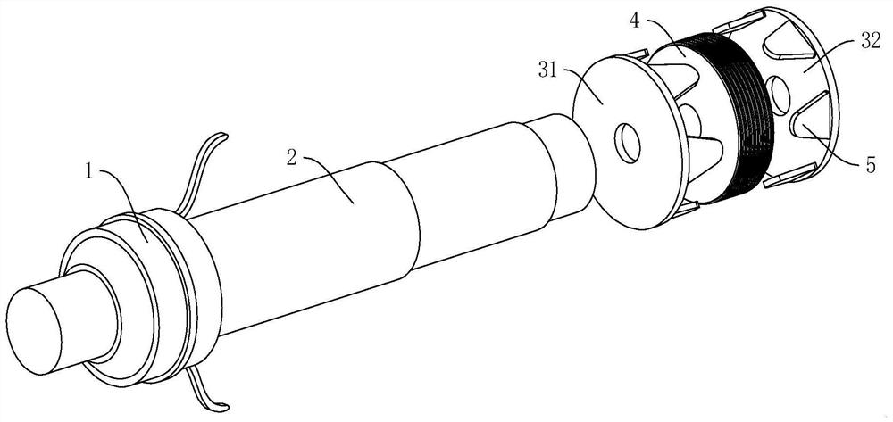
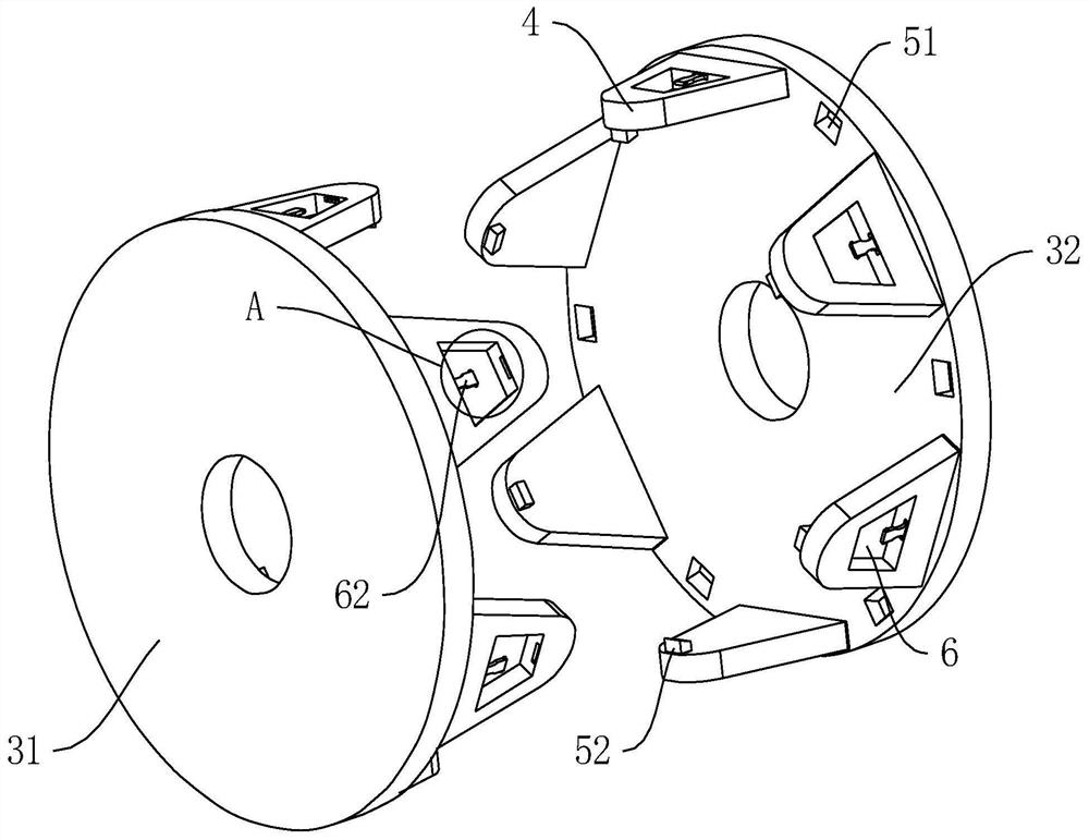
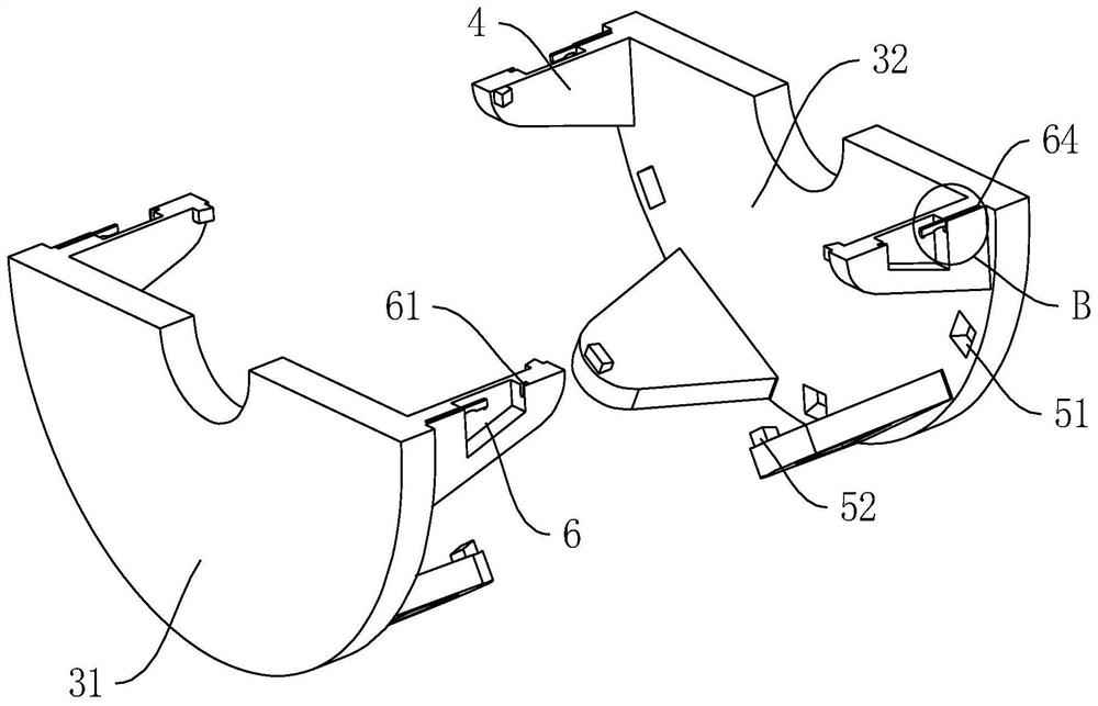
[0019] Such as Figure 1-5 A self-excited single-phase generator shown includes a collector ring 1, a rotor shaft 2, a front claw pole 31, a rear claw pole 32, a yoke 4, and claw pole fingers 5, and a front claw pole 31 and a rear claw pole 32 The size of the ...


PUM


Abstract

The invention discloses a self-excitation single-phase generator. The invention particularly relates to the technical field of excitation generators. The generator comprises a collecting ring, a rotorshaft, a front claw pole, a rear claw pole, a magnet yoke and claw pole fingers, the sizes of the claw pole fingers on the front claw pole and the rear claw pole are sequentially reduced in the direction of the opposite faces of the front claw pole and the rear claw pole, a distance groove matched with the size of each claw pole finger is formed between every two claw pole fingers, and a connecting groove and a connecting plate which enable the opposite ends of the claw pole fingers on the front claw pole and the rear claw pole to be connected at intervals are arranged between the claw pole fingers. According to the invention, the opposite ends of the claw pole fingers on the front claw pole and the rear claw pole are arranged at intervals, and the magnetic conductivity generated by permanent magnets on the claw pole fingers generates a magnetic conduction space in the interval grooves, so that the stability of the magnetic conductivity and no dead angle of the inverted conductor space of the permanent magnets is further ensured; while the permanent magnets in the claw pole fingers are detachably installed, compared with a traditional mode that the permanent magnets are directly attached to the claw pole fingers for installation, better fixing strength and stability are achieved.

Description

technical field [0001] The invention relates to the technical field of excitation generators, more specifically, the invention relates to a self-excitation single-phase generator. Background technique [0002] A generator is a mechanical device that converts other forms of energy into electrical energy. The generator excitation system is a general term for the power supply and its ancillary equipment that supply the excitation current of a synchronous generator. It generally consists of two main parts, the excitation power unit and the excitation regulator. [0003] The current self-excited single-phase generator rotor has permanent magnets embedded between the front and rear claw poles to increase the magnetic conductivity of the claw poles, but the position of the permanent magnets is unstable and directly affects the performance of the product, which increases the difficulty of assembly. Contents of the invention [0004] In order to solve the above technical problems,...

Claims


Application Information

Patent Timeline
IPC IPC(8): H02K1/24H02K1/28H02K1/27H02K19/28H02K21/12
CPCH02K1/243H02K1/28H02K1/27H02K19/28H02K21/12
Inventor 王远锋石斌
Owner 安徽德科电气科技有限公司
Why Eureka
Try Eureka