A heat exchanger steam sootblower

A soot blower and heat exchanger technology, applied in lighting and heating equipment, combustion product treatment, combustion methods, etc., can solve the problems of long-term safe and stable operation, dust in the heat exchange area, nozzle clogging and other problems, and achieve long-term guarantee The effect of stable operation, prevention of dust accumulation and blockage, and prevention of leakage

Active Publication Date: 2017-07-21
ZHEJIANG TIANDI ENVIRONMENTAL PROTECTION TECH CO LTD
View PDF10 Cites 0 Cited by
  • Summary
  • Abstract
  • Description
  • Claims
  • Application Information

AI Technical Summary

Problems solved by technology

Part of the flue gas cooler is arranged in front of the absorption tower. Long-term operation will easily cause dust accumulation on the heat exchange surface, which will affect the heat exchange efficiency.
[0003] In order to reduce the soot accumulation on the heat exchange tubes in the flue gas cooler, several semi-telescopic sootblowers are installed in the low temperature economizer or the flue gas heat exchanger, but because most of them have dead blowing angles, it is easy to cause the heat exchange surface jam
Installing a rake type soot blower is likely to cause nozzle blockage, and it is difficult to balance the pressure at each nozzle, and the blowing effect cannot be achieved

Method used


Image

  • A heat exchanger steam sootblower
  • A heat exchanger steam sootblower
  • A heat exchanger steam sootblower

Examples


Embodiment Construction

[0015] The present invention will be further described below in conjunction with the examples. The description of the following examples is provided only to aid the understanding of the present invention. It should be pointed out that for those skilled in the art, without departing from the principle of the present invention, some improvements and modifications can be made to the present invention, and these improvements and modifications also fall within the protection scope of the claims of the present invention.

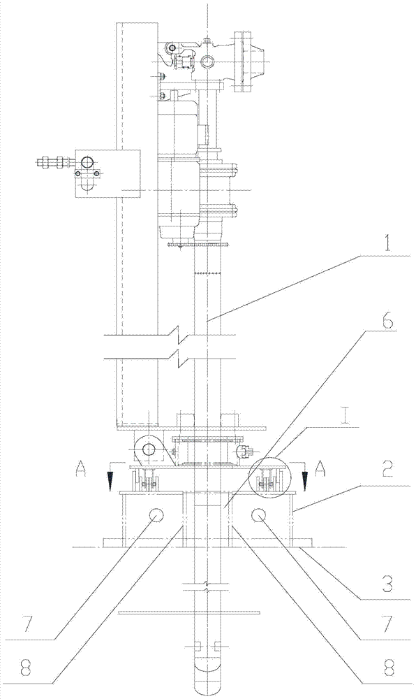
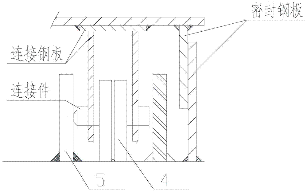
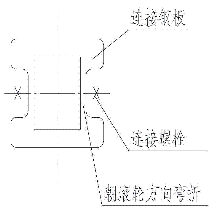
[0016] The heat exchanger steam soot blower includes a semi-telescopic soot blower 1, a soot blower support structure 2 and a flue top wall 3; the soot blower support structure 2 is arranged on the flue top wall 3; the flue There is a long notch on the wall 3 at the top of the channel. The soot blower support structure 2 is arranged on both sides of the notch and encloses a sealed air cavity 6. The soot blower support structure 2 is located on both sides of the no...


PUM


Abstract

The invention relates to a steam sootblower for a heat exchanger. The steam sootblower comprises a semi-telescopic sootblower body, sootblower supporting structures and a flue top wall surface, wherein the sootblower supporting structures are arranged on the flue top wall surface; a long through notch is formed in the flue top wall surface, the sootblower supporting structures are arranged at the two sides of the notch, and a sealed air cavity is defined by the sootblower supporting structures and the notch; hole-shaped structures are arranged on the inner walls of sootblower supporting frames, located at the two sides of the notch, of the sootblower supporting structures, and sealed air pipe inlet points are arranged in the inner walls of the sootblower supporting frames, located at the two sides of the notch, of the sootblower supporting structures; limiting guide rails are arranged on the upper end faces of the sootblower supporting structures; idler wheels matched with the limiting guide rails are arranged at the bottom of the semi-telescopic sootblower body; a soot blowing pipe of the semi-telescopic sootblower body stretches into the notch in the flue top wall surface. The steam sootblower has the beneficial effects that each steam sootblower is arranged to be movable and is used for blowing soot while moving, and the situation that a plurality of sootblowers are arranged on a single heat exchange surface for achieving the blowing effect is not needed; in addition, it can be better guaranteed that no dead corner exits on the whole heat exchange surface, and blockage of the heat exchange surface caused by soot accumulation is prevented.

Description

technical field [0001] The invention relates to a steam soot blower for a heat exchanger, in particular to a steam soot blower capable of fully covering the entire heat exchange surface of the heat exchanger. Background technique [0002] Many coal-fired power plants are equipped with low-temperature economizers or flue gas heat exchangers to realize waste heat recovery and utilization of flue gas, or to heat boiler feed water for energy-saving purposes, or to raise the exhaust gas temperature of chimneys to solve common problems in coal-fired power plants. The "gypsum rain" problem. Part of the flue gas cooler is arranged in front of the absorption tower. Long-term operation will easily cause dust accumulation on the heat exchange surface, which will affect the heat exchange efficiency. . [0003] In order to reduce the soot accumulation on the heat exchange tubes in the flue gas cooler, several semi-telescopic sootblowers are installed in the low temperature economizer o...

Claims


Application Information

Patent Timeline
Patent Type & Authority Patents(China)
IPC IPC(8): F23J3/02
CPCF23J3/02
Inventor 李清毅王汝能钟莎吴国潮孟炜朱松强胡达清高翔俞峰苹郑成航
Owner ZHEJIANG TIANDI ENVIRONMENTAL PROTECTION TECH CO LTD
Why Eureka
Try Eureka