Rail fastening system

A technology for fixing systems and guide rails, which is applied in the direction of fixing rails, tracks, friction-clamped detachable fasteners, etc., and can solve problems such as concrete main body damage

Active Publication Date: 2020-10-20
SCHWIHAG
View PDF12 Cites 0 Cited by
  • Summary
  • Abstract
  • Description
  • Claims
  • Application Information

AI Technical Summary

Problems solved by technology

However because the pins are locked in the backing plate from below and are poured deep into the concrete, this dismantling can lead to severe damage to the concrete body

Method used


Image

  • Rail fastening system
  • Rail fastening system
  • Rail fastening system

Examples


Embodiment Construction

[0024] A preferred exemplary embodiment is described below with the aid of figures. In this case, identical, similar or identically acting elements are provided with the same reference symbols in the figures, and a repeated description of these elements is partially omitted in order to avoid redundancy.

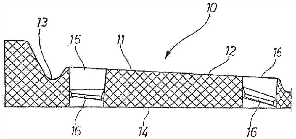
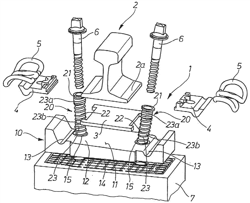
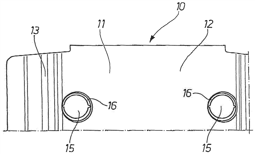
[0025] figure 1 Shown is a rail fastening system 1 with a backing plate 10 and two pins 20 connected thereto.

[0026] In the present exemplary embodiment, the backing plate 10 is a mounting plate with a contoured mounting surface 11 for fastening the rail 2 . For this purpose, the mounting surface 11 has an inclined guide rail bearing section 12 , on which the guide rail 2 rests in the fixed state, optionally via a vibration-damping and / or elastic intermediate layer 3 . Furthermore, the mounting surface 11 has a receptacle 13 which is provided for receiving the angle guide 4 . The angle guide plate 4 is in turn used together with the clamping clip 5 , which is a bent stee...


PUM


Abstract

The invention relates to a rail fastening system (1) for fastening a rail (2) on a rail underlying surface, preferably for a solid roadway, which rail fastening system has a base plate (10), preferably made of plastic, and at least one dowel (20), wherein the base plate (10) has at least one opening (15), which penetrates the base plate (10) completely in the thickness direction, and wherein the dowel (20) is introduced into the opening (15), is retained therein by means of a retaining contour and, in the thickness direction, projects above the base plate (10), at least on one side.

Description

technical field [0001] The invention relates to a rail fastening system for fastening a rail to a rail base (Schienenuntergrund), preferably for a ballastless track (feste Fahrbahn), which has a backing plate with at least one opening and at least one pins in. Furthermore, the invention relates to a method for producing a rail fastening system. Background technique [0002] Backing plates are used for fastening the railroad rails to the rail base for ballastless tracks, which can be embodied, for example, as mounting plates, system frames or inclined plates. [0003] DE 20 2015 103 972 U1 thus describes a mounting plate equipped with pins for locking in a concrete bed and for mounting rail holding means. On the bottom side, the mounting plate has a bearing surface for attachment to the load-bearing structure. In order to preassemble a pin (like several pins) on the mounting plate, the pin head is introduced from the side of the bearing surface into a corresponding opening...

Claims


Application Information

Patent Timeline
Patent Type & Authority Applications(China)
IPC IPC(8): E01B9/18E01B9/38F16B13/00F16B13/14
CPCE01B9/18E01B9/38E01B9/14F16B13/00F16B5/125F16B2/065E01B9/28E01B2204/09
Inventor S.利恩哈德F.迈尔
Owner SCHWIHAG
Why Eureka
Try Eureka