Motor rotor and magnetizing method thereof

A technology of motor rotor and rotor core, applied in the manufacture of stator/rotor body, magnetic circuit rotating parts, magnetic circuit shape/style/structure, etc. Impact and other problems, to achieve the effect of ensuring magnetization saturation, providing reliability, and good coaxiality

Active Publication Date: 2018-11-13
GREE ELECTRIC APPLIANCES INC
View PDF6 Cites 0 Cited by
  • Summary
  • Abstract
  • Description
  • Claims
  • Application Information

AI Technical Summary

Problems solved by technology

In this way, when the winding of the electronic stator passes a large current, the enameled wire will be impacted by the instantaneous short-term current, and the enameled wire may break down, reducing the life of the motor
At the same time, due to the inconsistent height difference of the rotor, the magnetization of the rotor magnet will not be saturated.

Method used


Image

  • Motor rotor and magnetizing method thereof
  • Motor rotor and magnetizing method thereof
  • Motor rotor and magnetizing method thereof

Examples


Embodiment Construction

[0037] In order to make the technical solution of the present invention clearer, the motor rotor and its magnetizing method of the present invention will be further described in detail below in conjunction with the accompanying drawings. It should be understood that the specific embodiments described here are only used to explain the present invention and not to limit the present invention. It should be noted that, in the case of no conflict, the embodiments in the present application and the features in the embodiments can be combined with each other.

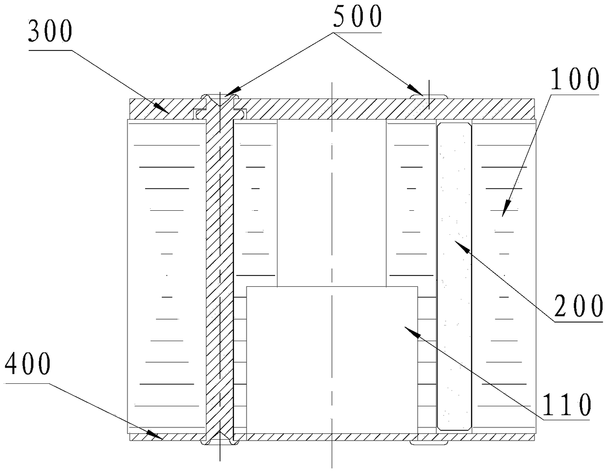
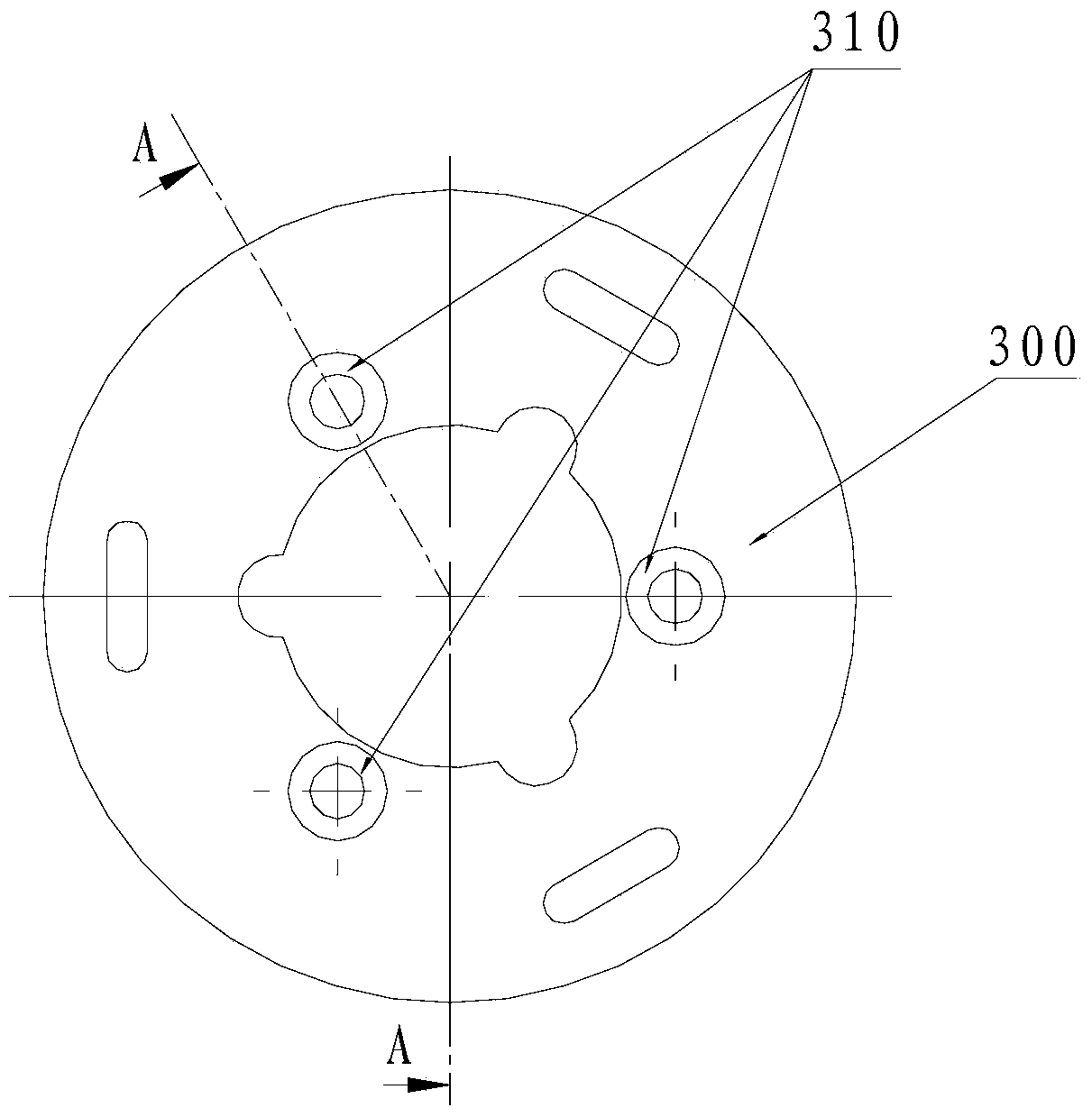
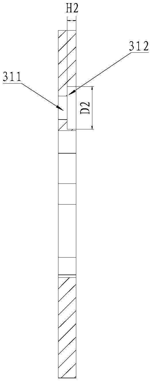
[0038] see Figure 1 to Figure 6 ,like figure 1 As shown, the motor rotor of the present invention includes a rotor core 100 , a magnetic steel 200 , a first baffle 300 , a second baffle 400 and a fastener 500 . Wherein, the rotor core 100 is provided with magnetic steel grooves, and the magnetic steel 200 is arranged in the magnetic steel grooves alternately according to N poles and S poles. In this embodiment, the shape o...


PUM


Abstract

The invention provides a motor rotor. The motor rotor comprises a rotor core, magnetic steel, a first baffle, a second baffle, and fasteners, the first baffle is arranged at a first end of the rotor core, the first baffle is provided with counterbores for limiting the fasteners, each fastener comprises three segments in the length direction, the diameter of the second segment of the fastener is greater than the diameters of the first segment and the third segment of the fastener, the second segments of the fasteners are arranged in the counterbores, the second baffle is arranged at a second end of the rotor core, the second baffle is provided with through holes in a corresponding manner, the third segments of the fasteners can penetrate through the through holes, and the first baffle and the second baffle are fixed on the rotor core through the fasteners. The invention also provides a magnetizing method of the motor rotor. According to the motor rotor and the magnetizing method thereof, good coaxiality of the rotor and a crankshaft is guaranteed, magnetizing saturation of the magnetic steel is ensured, the magnetizing process is optimized, and the performance and the reliability of the motor are improved.

Description

technical field [0001] The invention relates to the technical field of variable frequency motors, in particular to a motor rotor and a magnetizing method thereof. Background technique [0002] Generally, the magnetic steel of the rotor assembly is axially positioned with the rotor core through two upper and lower baffles, and the upper second baffle is used to block the magnetic steel to prevent the magnetic steel from flying out during the operation of the rotor. The upper second baffle passes through the rotor core through three symmetrical rivets and is riveted together. [0003] The assembly and magnetization methods of the general rotor assembly are as follows: [0004] 1. After the magnetic steel is magnetized, it is placed in the rotor core and positioned by the upper second baffle to complete the assembly of the rotor assembly, and then press the assembled rotor assembly onto the crankshaft of the compressor cylinder block under normal temperature (cold pressure). ...

Claims


Application Information

Patent Timeline
Patent Type & Authority Patents(China)
IPC IPC(8): H02K1/27H02K1/28H02K15/03
Inventor 吴广荣陈华杰
Owner GREE ELECTRIC APPLIANCES INC
Why Eureka
Try Eureka