Disposable pipeline integrated pump head split micropump

An integrated pump, one-time technology, applied in the direction of liquid displacement machinery, pumps with flexible working elements, pumps, etc., can solve the problems of inconvenient disinfection and cleaning, pollution, pipeline movement, etc., to improve the success of experiments efficiency, reduce the risk of contamination, and stabilize the pipeline

Active Publication Date: 2017-09-15
SCI RES TRAINING CENT FOR CHINESE ASTRONAUTS
View PDF8 Cites 0 Cited by
  • Summary
  • Abstract
  • Description
  • Claims
  • Application Information

AI Technical Summary

Problems solved by technology

At present, conventional peristaltic pumps are large in size, and it is difficult to integrate them into other equipment; especially, the pump heads and pipelines equipped with conventional peristaltic pumps have to be reused many times, which is not convenient for disinfection and cleaning. It brings the risk of exogenous impurities and pollution, which is not suitable for applications requiring high experimental success rates; and the rollers of the pump head in the existing peristaltic pumps are cylindrical, and some of the pipelines have no special positioning structure, resulting in The pipeline may move during the operation of the pump, resulting in a change in the flow rate in the experiment, which is not suitable for experiments requiring accurate flow rate; the existing peristaltic pump structure is not suitable for long-term integration of the pipeline into the pump head, which will cause Long-term compression of the pipeline and sticky blockage

Method used


Image

  • Disposable pipeline integrated pump head split micropump
  • Disposable pipeline integrated pump head split micropump
  • Disposable pipeline integrated pump head split micropump

Examples


Embodiment Construction

[0025] The specific embodiments of the present invention will be described in further detail below in conjunction with the drawings and embodiments. The following examples are used to illustrate the present invention, but not to limit the scope of the present invention.

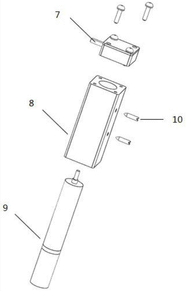
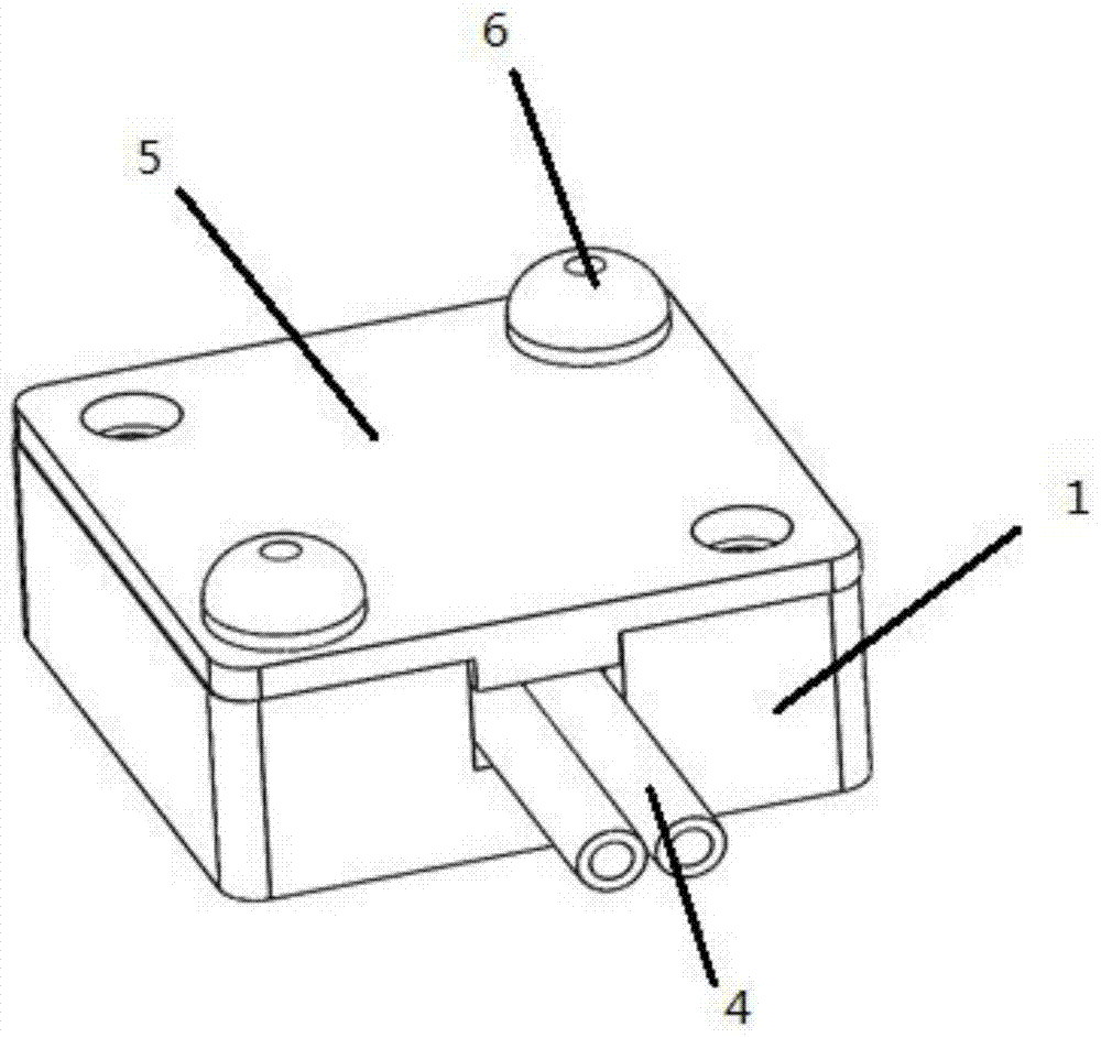
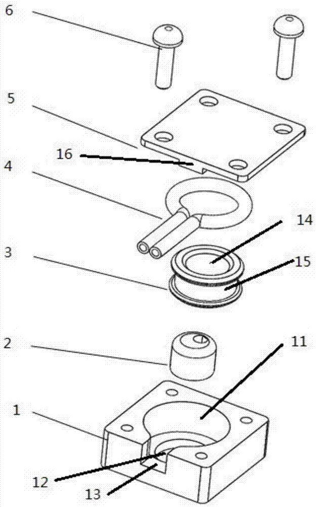
[0026] See figure 1 , figure 2 and image 3 , The disposable pipeline integrated pump head split micropump of the present invention includes a pump body 8, a motor 9 and a pump head pipeline assembly 7. The motor 9 is installed in the center hole of the pump body 8 and uses 2 M2 set screws 10Fixed; the pump head pipeline assembly 7 is installed on the upper surface of the pump body 8 with 2 M2 screws, and the motor shaft extends into the pump head pipeline assembly 7; the pump head pipeline assembly 7 is disposable, the pump head pipeline assembly 7 Including the pump head seat 1, the eccentric wheel 2, the pump head roller 3 and the circumferential compression pipeline 4, the circumferential compression pipel...


PUM


Abstract

The invention relates to a split type miniature peristaltic pump, in particular to a miniature peristaltic pump, wherein a pipeline is integrated to a pump head, and both the pump head and the pipeline can be used for one time. The micropump comprises a pump body, a motor and a pump head and pipeline assembly. The pump head and pipeline assembly comprises a pump head seat, an eccentric wheel, a pump head roller and a circumferential pressing pipeline; a pump head seat center hole is formed in the pump head seat, a through hole is coaxially formed in the bottom of the pump head seat center hole, and a pipeline inlet / outlet groove is formed in one side of the pump head seat; the pump head roller is arranged in the pump head seat center hole, a pump head roller center hole is formed in the pump head roller, and the eccentric wheel is arranged in the pump head roller center hole and connected with an output shaft of the motor through an eccentric hole; and a pump head roller groove is formed in the outer wall of the pump head roller, and the circumferential pressing pipeline is sleeved with the pump head roller groove along the outer wall of the pump head roller. According to the micropump, the structure of the assembly formed by the pump head and the pipeline can guarantee that the pump is compact in structure and small in size; and the single-use purpose can be achieved, the pollution risk is lowered effectively, and the experiment success rate is increased to a great extent.

Description

Technical field [0001] The invention relates to a split type micro peristaltic pump, in particular, the pipeline has been integrated on the pump head, and the pump head is a micro peristaltic pump that can be used with the pipeline at one time. Background technique [0002] Currently, peristaltic pumps are one of the most frequently used devices in cell biology, life sciences and related medical research fields. At present, conventional peristaltic pumps are large in size and it is difficult to integrate them into other equipment; in particular, the pump head and pipelines equipped with conventional peristaltic pumps have to be reused many times, which is not convenient for disinfection and cleaning, and may be used in subsequent experiments. Bringing the risk of external impurities and pollution, this is not suitable for applications with high experimental success rate; and the existing peristaltic pump has a cylindrical pump head roller, and there is no special positioning stru...

Claims


Application Information

Patent Timeline
Patent Type & Authority Patents(China)
IPC IPC(8): F04B43/12
CPCF04B43/1238
Inventor 谭映军王春艳施镠佳于建茹聂捷琳顾寅万玉民李莹辉殷学民曹宏卿
Owner SCI RES TRAINING CENT FOR CHINESE ASTRONAUTS
Why Eureka
Try Eureka