
Medical equipment sterilizing equipment

A technology for disinfection equipment and medical equipment, applied in the direction of disinfection, chemical instruments and methods, chemistry, etc., can solve problems that affect actual use and increase working hours

Inactive Publication Date: 2020-10-23
鲍玉梅
View PDF7 Cites 2 Cited by
  • Summary
  • Abstract
  • Description
  • Claims
  • Application Information

AI Technical Summary

Problems solved by technology

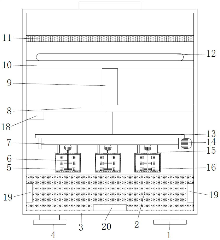
[0005] The purpose of the present invention is to provide a medical instrument disinfection equipment, which has the advantages of intelligent control of the present invention through an external terminal link to the Internet of Things, intelligent and convenient operation, and the auxiliary cleaning function of ultrasonic cleaning and heating cleaning, so that the disinfection The advantages of more thoroughness and better practicability solve the problem that the existing medical device disinfection equipment can only sterilize the surface bacteria when it is used, resulting in the need for personnel to perform manual disinfection again in the later stage, which affects the actual use and increases the working time.

Method used


Image

  • Medical equipment sterilizing equipment
  • Medical equipment sterilizing equipment
  • Medical equipment sterilizing equipment

Examples


Embodiment Construction

[0029] The following will clearly and completely describe the technical solutions in the embodiments of the present invention with reference to the accompanying drawings in the embodiments of the present invention. Obviously, the described embodiments are only some, not all, embodiments of the present invention. Based on the embodiments of the present invention, all other embodiments obtained by persons of ordinary skill in the art without making creative efforts belong to the protection scope of the present invention.

[0030] In the description of the present invention, it should be noted that the terms "upper", "lower", "inner", "outer", "front end", "rear end", "both ends", "one end", "another end" The orientation or positional relationship indicated by etc. is based on the orientation or positional relationship shown in the drawings, and is only for the convenience of describing the present invention and simplifying the description, rather than indicating or implying that ...


PUM


Abstract

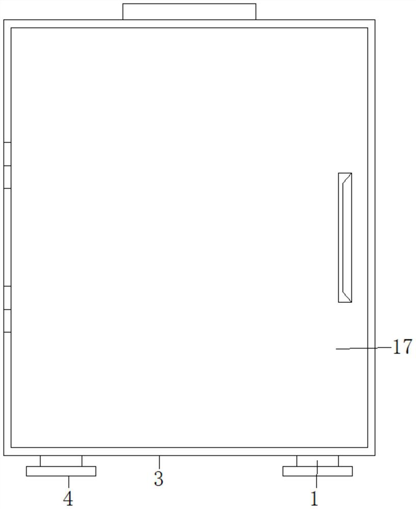
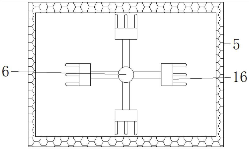
The invention discloses medical equipment sterilizing equipment. The medical equipment sterilizing equipment comprises a housing, a filter screen box, a fixed frame and a connecting plate, wherein theinner wall of the housing is welded with the fixed frame and the connecting plate; the top end surface of the connecting plate is equipped with an electric heating wire in a fitted mode; the inner wall of the housing is fixedly provided with the filter screen board; the outer surface of the housing is equipped with a cover plate through a hinge; a holding handle is mounted on the cover plate; thetop end surface of the fixed frame is fixedly provided with a gas cylinder; a limiting frame is mounted on the output shaft of the gas cylinder; the bottom end surface of the limiting frame is weldedwith a connecting frame; the inner wall of the connecting frame is rotatably equipped with a second rotary shaft; the bottom end surface of the second rotary shaft is equipped with the filter screenbox through a limiting rod; a first rotary shaft is rotatably mounted in the filter screen box; the two ends of the first rotary shaft are welded with brushes; the bottom end surface of the inner wallof the housing is fixedly equipped with a box body; the filter screen box is mounted in the box body; the lower part of the inner side wall of the housing and the inner side of the bottom wall of thehousing are further provided with an ultrasonic generator and a heating device; and a liquid level height sensor is further arranged on the lower part of the fixed frame. An external terminal is linked with the internet of things to intelligently control, so that the medical equipment sterilizing equipment has the advantages of being intelligent and convenient in operation, more complete in sterilizing and better in practicability.

Description

technical field [0001] The invention relates to the technical field of medical device disinfection, in particular to a medical device disinfection device. Background technique [0002] Medical device disinfection equipment refers to: medical devices refer to instruments, equipment, utensils, in vitro diagnostic reagents and calibrators, materials, and other similar or related items that are directly or indirectly used on the human body, including required computer software. The effect is mainly obtained through physical methods, not through pharmacological, immunological or metabolic methods, or although these methods are involved, they only play an auxiliary role. The purpose is diagnosis, prevention, monitoring, treatment or mitigation of disease; diagnosis, monitoring, treatment, mitigation or functional compensation of injury. [0003] After searching a large number of patent documents, it is known that: Chinese invention patent: application number [CN201110429031.5], p...

Claims


Application Information

Patent Timeline
IPC IPC(8): B08B1/04B08B3/08B08B3/10B08B3/12B08B13/00A61L2/04A61L2/18
CPCB08B3/08B08B3/12B08B3/106B08B13/00A61L2/04A61L2/18A61L2202/17A61L2202/24B08B1/12B08B1/32
Inventor 鲍玉梅
Owner 鲍玉梅
Learn More