Vacuum perfusion process for making composite flywheel rotor or part of rotor

A composite material and flywheel rotor technology, which is applied in the field of vacuum infusion technology, can solve the problems of composite material flywheel rotor or part of the rotor quality stability and FWF stability are difficult to guarantee.

Inactive Publication Date: 2020-10-23
蔡祯祺
View PDF0 Cites 0 Cited by
  • Summary
  • Abstract
  • Description
  • Claims
  • Application Information

AI Technical Summary

Problems solved by technology

However, in the current composite dry or wet overall and resin curing molding technology, it is difficult

Method used


Image

  • Vacuum perfusion process for making composite flywheel rotor or part of rotor
  • Vacuum perfusion process for making composite flywheel rotor or part of rotor

Examples


Embodiment 1

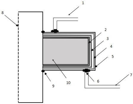
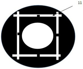
[0015] refer to Figure 1-2 , use carbon fiber or carbon-glass blended yarn / cloth to wrap around the specified inner cavity mold 8 under the tension of 145N-175N, and fix it with resin nails. At the end of carbon fiber or carbon-glass blended yarn / cloth, lay isolation film 2, guide net 3, and non-grinding cloth 4, and lay Ω vacuum perfusion pipe 11 at the center of the outer side, and three-way valve 6 respectively installed in the inner cavity The top and bottom of the mold 8 are connected to the position of the Ω vacuum perfusion tube 11 . The three-way valve 6 arranged above the inner cavity mold 8 is connected to the feeding pipe 1, and the three-way valve 6 arranged below the inner cavity mold 8 is connected to the vacuum pipe 7; a vacuum belt 5 is laid on the outside of the semi-permeable membrane and the Ω vacuum perfusion tube, The Ω vacuum perfusion tube 11 exposes the vacuum belt 5, and a sealing tape 9 is used to ensure airtightness. The other side of the three-wa...


PUM


Abstract

The invention discloses a vacuum perfusion process for making a composite flywheel rotor or part of the rotor. A composite matrix used for making the flywheel rotor is vacuum-perfused with resin andcured to form a glass fiber reinforced plastics body with high strength. The vacuum perfusion method can enhance the impact resistance of the flywheel rotor or part of the rotor, greatly improve the angular speed of the flywheel rotor, and improve the energy storage density of the flywheel rotor.

Description

technical field [0001] The invention relates to a vacuum infusion technology for a composite material flywheel rotor or part of the rotor. This vacuum infusion method will improve the impact resistance of the flywheel rotor or part of the rotor, greatly increase the angular velocity of the flywheel rotor, and increase the energy storage density of the flywheel rotor. Background technique [0002] The increase in the angular velocity of the flywheel rotor has always been an important part of flywheel energy storage, and the application of composite materials helps to increase the angular velocity of the rotor made of metal materials. However, in the current composite dry or wet overall and resin curing molding technology, it is difficult to guarantee the quality stability and FWF stability of the composite flywheel rotor or part of the rotor. The application of this technology will greatly improve the stability of the composite flywheel rotor or part of the rotor and the cons...

Claims


Application Information

Patent Timeline
IPC IPC(8): B29C70/44B29C70/54
CPCB29C70/443B29C70/54B29L2031/7498
Inventor 蔡祯祺
Owner 蔡祯祺
Why Eureka
Try Eureka