Circuit board and protective film pasting device and pasting method

A circuit substrate and mounting device technology, which is applied in the field of circuit substrate protective film mounting devices, can solve the problems of affecting the accuracy of protective film mounting, increasing the time of protective film mounting, and warping and deformation of the protruding end of the protective film.

Inactive Publication Date: 2020-10-23
潘丽君
View PDF0 Cites 0 Cited by
  • Summary
  • Abstract
  • Description
  • Claims
  • Application Information

AI Technical Summary

Problems solved by technology

[0003] The prior art has the following deficiencies: 1. When feeding the protective film, after the cut-off module cuts off the protective film, there is a certain distance between the protruding end of the protective film and the pressing end of the protective film. This section of the protective film is a free section for the next The station mechanism grabs the protective film; and because the material of the protective film is soft, the protruding end of the protective film will be warped and deformed by the air circulation in the space, making the protruding end of the protective film relative to the next station. The position of the mechanism changes, which affects the accuracy of the protective film placement
2. When attaching the protective film to the circuit substrate, the movement of the circuit substrate drives the protective film wound on the winding drum to move accordingly to attach the protective film to the circuit substrate; and the circuit substrate is large in size, in order to ensure that the circuit The substrate moves smoothly, and the circuit substrate can only move at a lower speed when moving, which makes the process of mounting the protective film longer and increases the mounting time of the protective film

Method used


Image

  • Circuit board and protective film pasting device and pasting method
  • Circuit board and protective film pasting device and pasting method
  • Circuit board and protective film pasting device and pasting method

Examples


Embodiment 1

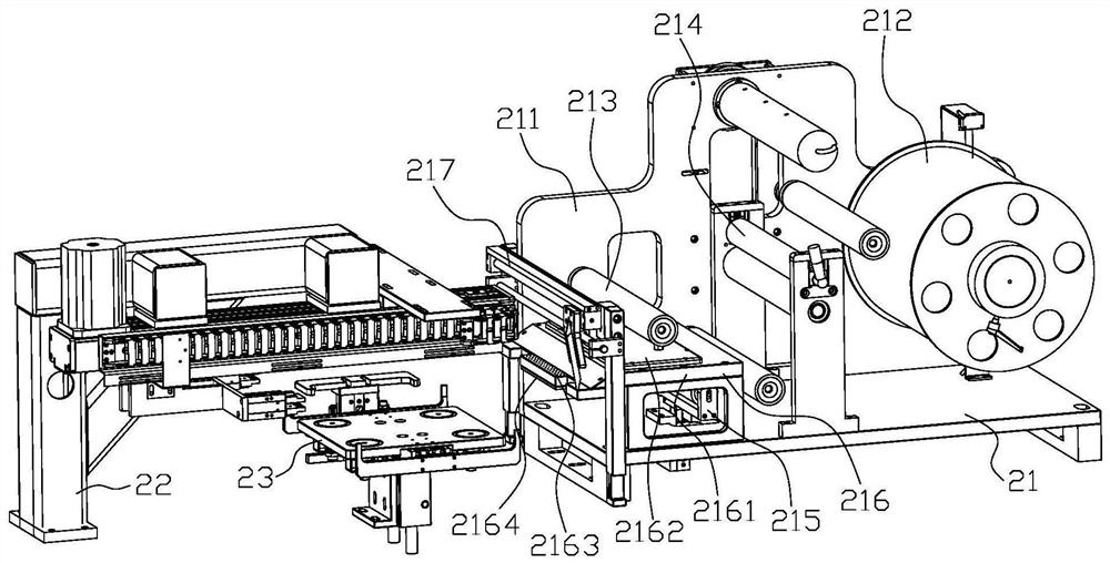
[0024] Such as figure 1 The shown circuit substrate protective film mounting device includes a film feeding mechanism 21, a film pulling mechanism 22 and a lifting mechanism 23; the film feeding mechanism 21, the film pulling mechanism 22 and the lifting mechanism 23 are all fixed on the workbench; The outlet of the film feeding mechanism 21 is connected with the film pulling mechanism 22; the film pulling mechanism 22 is located above the upper top mechanism 23 and the film pulling mechanism 22 is connected with the upper top mechanism 23; the film feeding mechanism 21 is used for feeding the protective film; The film pulling mechanism 22 is used to pull out the protective film; the lifting mechanism 23 is used to lift the circuit substrate.

[0025] The film supply mechanism 21 includes a film supply frame 211 and a coil material drum 212 fixed on the film supply frame 211, a film supply roller 213, a film pressing assembly 214, a stretching assembly 215, a suction film asse...


PUM


Abstract

The invention relates to the field of circuit boards. The circuit board and protective film pasting device comprises a film feeding mechanism, a film pulling mechanism and an upper jacking mechanism.The film feeding mechanism, the film pulling mechanism and the upper jacking mechanism are all fixed to a workbench. A discharging opening of the film feeding mechanism is connected with the film pulling mechanism. The film pulling mechanism is located above the upper jacking mechanism and is connected with the upper jacking mechanism. According to the device, the relative position between a circuit board and a protective film is guaranteed to be accurate during pasting by arranging the film feeding mechanism; and by arranging the film pulling mechanism and the upper jacking mechanism, the pasting time of the protective film is shortened.

Description

technical field [0001] The invention relates to the field of circuit substrates, in particular to a circuit substrate protective film mounting device and mounting method. Background technique [0002] Circuit substrate products are composed of circuit substrate, positioning jig and protective film: the positioning jig is fixed on both sides of the circuit substrate and connected with the circuit substrate; the protective film is attached to the surface of the circuit substrate and does not contact the positioning jig. The following steps are mainly included in the process of circuit substrate film sticking: 1) Put the circuit substrate and the positioning fixture connected to it into the storage mechanism, and the storage mechanism will move it and control the output of the circuit substrate; 2) The storage mechanism Push the circuit substrate to the blanking mechanism, and the blanking mechanism quickly blanks the circuit substrate; 3) The circuit substrate is blanked to th...

Claims


Application Information

Patent Timeline
IPC IPC(8): B65B33/02B65B41/14B65B41/16B65B61/06
CPCB65B33/02B65B41/14B65B41/16B65B61/06
Inventor 潘丽君齐磊莹
Owner 潘丽君
Why Eureka
Try Eureka