Small cargo handling device
A technology for handling devices and goods, applied in the field of small cargo handling devices, can solve the problems of time-consuming, labor-consuming and the like
- Summary
- Abstract
- Description
- Claims
- Application Information
AI Technical Summary
Problems solved by technology
Method used
Image
Examples
Embodiment 1
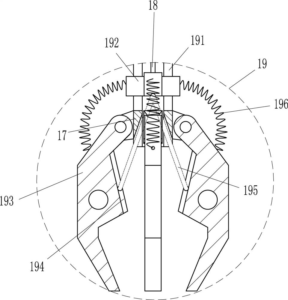
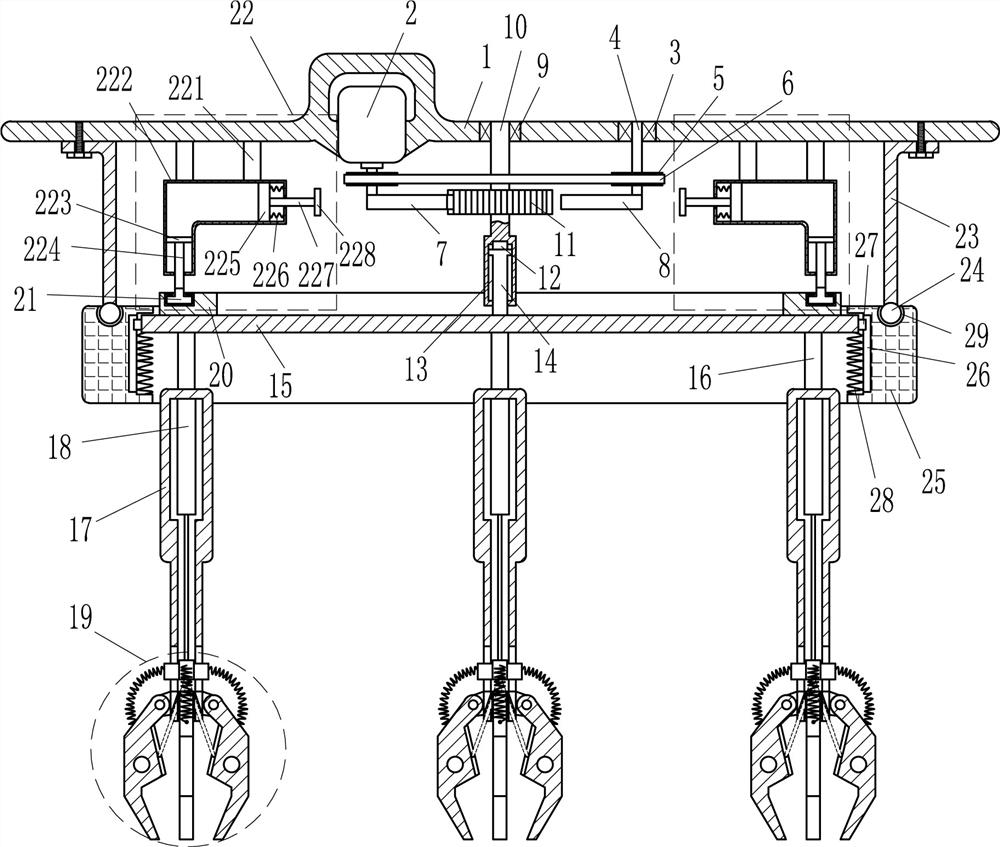
[0014] A small cargo handling device such as Figure 1-2 As shown, it includes a top plate 1, a motor 2, a first bearing seat 3, a first shaft 4, a pulley 5, a flat belt 6, a sector gear 7, a sector block 8, a second bearing seat 9, a second shaft 10, and all gears 11. Guide rod 14, circular plate 15, fixed rod 16, cylindrical hollow body 17, electric push rod 18, clamping device 19, ring slide rail 20, first slider 21 and lifting device 22, top plate 1 bottom left The motor 2 is installed on the side, and the top plate 1 is connected with the motor 2 through bolt connection. The first bearing seat 3 is provided on the right part of the top plate 1, and the first rotating shaft is provided in the first bearing seat 3 and on the output shaft at the bottom of the motor 2. 4. Pulleys 5 are provided on the first rotating shaft 4, and flat belts 6 are wound between the pulleys 5 on the left and right sides. The bottom end of the first rotating shaft 4 on the left is provided with a...
Embodiment 2
[0016] A small cargo handling device such as Figure 1-2 As shown, it includes a top plate 1, a motor 2, a first bearing seat 3, a first shaft 4, a pulley 5, a flat belt 6, a sector gear 7, a sector block 8, a second bearing seat 9, a second shaft 10, and all gears 11. Guide rod 14, circular plate 15, fixed rod 16, cylindrical hollow body 17, electric push rod 18, clamping device 19, ring slide rail 20, first slider 21 and lifting device 22, top plate 1 bottom left A motor 2 is installed on the side, and the right part of the top plate 1 is provided with a first bearing seat 3, and a first rotating shaft 4 is provided in the first bearing seat 3 and on the output shaft at the bottom of the motor 2, and a pulley 5 is provided on the first rotating shaft 4. , a flat belt 6 is wound between the pulleys 5 on the left and right sides, a sector gear 7 is provided at the bottom of the first rotating shaft 4 on the left side, a fan-shaped block 8 is provided at the bottom end of the f...
Embodiment 3
[0019] A small cargo handling device such as Figure 1-2As shown, it includes a top plate 1, a motor 2, a first bearing seat 3, a first shaft 4, a pulley 5, a flat belt 6, a sector gear 7, a sector block 8, a second bearing seat 9, a second shaft 10, and all gears 11. Guide rod 14, circular plate 15, fixed rod 16, cylindrical hollow body 17, electric push rod 18, clamping device 19, ring slide rail 20, first slider 21 and lifting device 22, top plate 1 bottom left A motor 2 is installed on the side, and the right part of the top plate 1 is provided with a first bearing seat 3, and a first rotating shaft 4 is provided in the first bearing seat 3 and on the output shaft at the bottom of the motor 2, and a pulley 5 is provided on the first rotating shaft 4. , a flat belt 6 is wound between the pulleys 5 on the left and right sides, a sector gear 7 is provided at the bottom of the first rotating shaft 4 on the left side, a fan-shaped block 8 is provided at the bottom end of the fi...
PUM
 Abstract
Description
Claims
Application Information
 - R&D
- Intellectual Property
- Life Sciences
- Materials
- Tech Scout
- Unparalleled Data Quality
- Higher Quality Content
- 60% Fewer Hallucinations
Browse by: Latest US Patents, China's latest patents, Technical Efficacy Thesaurus, Application Domain, Technology Topic, Popular Technical Reports.
© 2025 PatSnap. All rights reserved.Legal|Privacy policy|Modern Slavery Act Transparency Statement|Sitemap|About US| Contact US: help@patsnap.com


