Quick release joint system for assembling frames

a frame and joint technology, applied in the direction of rod connections, manufacturing tools, building scaffolds, etc., can solve the problems of no longer tight joints and useless frames, and achieve the effects of reducing the number and complexity of parts, improving functionality, and improving safety and reliability

Active Publication Date: 2015-02-17
MOSS HLDG
View PDF39 Cites 5 Cited by
  • Summary
  • Abstract
  • Description
  • Claims
  • Application Information

AI Technical Summary

Benefits of technology

[0005]In embodiments, a frame joint system is provided. Embodiments of the frame joint system find utility in many applications where rigid corners and other frame intersections are desired. Embodiments of the frame joint system include a quick release coupling to secure a mitered corner joint or other frame joints together. In some embodiments the quick release coupling includes first and second sleeve members and a gripping member. The frame joint system provides improvements in safety, reliability, ruggedness, ease of assembly and disassembly, rigidity, ease of manufacturing, and functionality. Embodiments provide improved functionality, particularly when the embodiments are used in temporary display systems that are frequently moved, erected, handled, and disassembled. Improvements are achieved by reducing the number and complexity of the parts, which improves reliability and reduces cost. A minimum number of operations are required to manufacture and install the components, thus reducing costs and improving quality. Simplicity of assembly and disassembly, rigidity, and durability are of great significance in certain applications such as, for example, temporary displays.
[0006]In embodiments that are particularly suited for use, among other uses, in frames in temporary displays, the frame joint system allows the quick and repeated erection, handling, and disassembly of even large display frames in the order of six feet by ten feet, or larger. The existence of rigid joints permits the handling of an assembled frame without damaging it.
[0007]The elements of a quick release coupling are generally permanently assembled to frame members so there are no loose parts to keep track of as the disassembled frame is moved from one location to another. In particular embodiments, for example, once the mitered ends of the respective frame members are brought into alignment with one another, a twist of a simple hand tool moves gripping elements in a gripping member between disengaged and engaged configurations. This locks the frame members into an assembled relationship. According to certain embodiments, similarly assembling three other joints between frame members quickly and easily secures the frame members into a substantially rigid generally rectangular frame. The assembly of the entire frame typically takes less than a minute. Disassembly is generally even quicker.
[0008]In embodiments, rigidity in the assembled joints is accomplished by using a quick release coupling in which, among other things, the area of gripping engagement is removed both spatially and angularly from the plane of the joint, and the gripping elements themselves are substantially protected from torsional forces. According to certain embodiments this spatial and angular separation from the joint plane is accomplished by the use of a quick release coupling that includes sleeve members nested in frame members, and a gripping member nested in a sleeve member. The gripping member is quickly actuatable between engaged and disengaged configurations.
[0013]According to certain embodiments, a quick disconnect gripping member takes the form, for example, of a cassette member that is axially slidably received and retained in the sleeve cavity in the first sleeve member. The retention of the gripping member in the sleeve cavity is permanent in the sense that it need not be removed from the sleeve cavity when the frame joint system is disassembled.
[0018]In certain embodiments, the frame joint extends at approximately 45 degrees to the longitudinal axes of the mated frame members. According to further embodiments, the gripping member is axially slidably received and releasably retained in the sleeve cavity. According to some embodiments, the first and second sleeve members are substantially shorter than the first and second frame members in which they are mounted. In general, the respective sleeve members need only be of sufficient axial length so that when retained in the respective frame cavities and releasably engaged in a joint system, they are substantially prevented from lateral or rotational movement in the respective frame members in which they are nested.

Problems solved by technology

If the fingers or brackets failed, the entire frame became useless until they were repaired.
The attachment locations of the brackets and fingers on the respective frame members tended to become worn so the joints could no longer be made tight.
Various previous expedients for joining frame components at locations other than at corner joints have presented similar deficiencies.

Method used


Image

  • Quick release joint system for assembling frames
  • Quick release joint system for assembling frames
  • Quick release joint system for assembling frames

Examples


Embodiment Construction

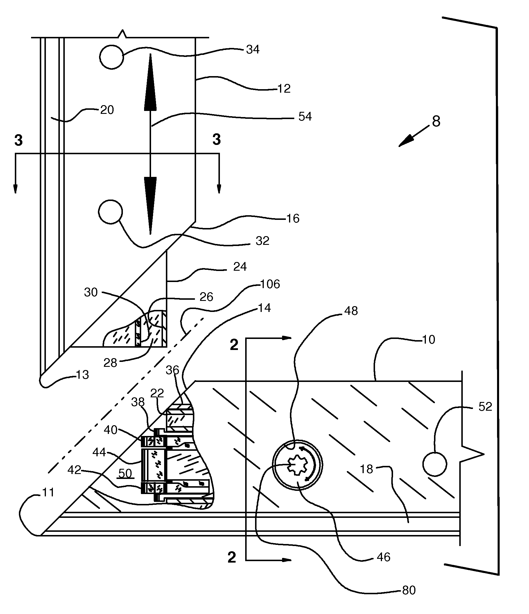
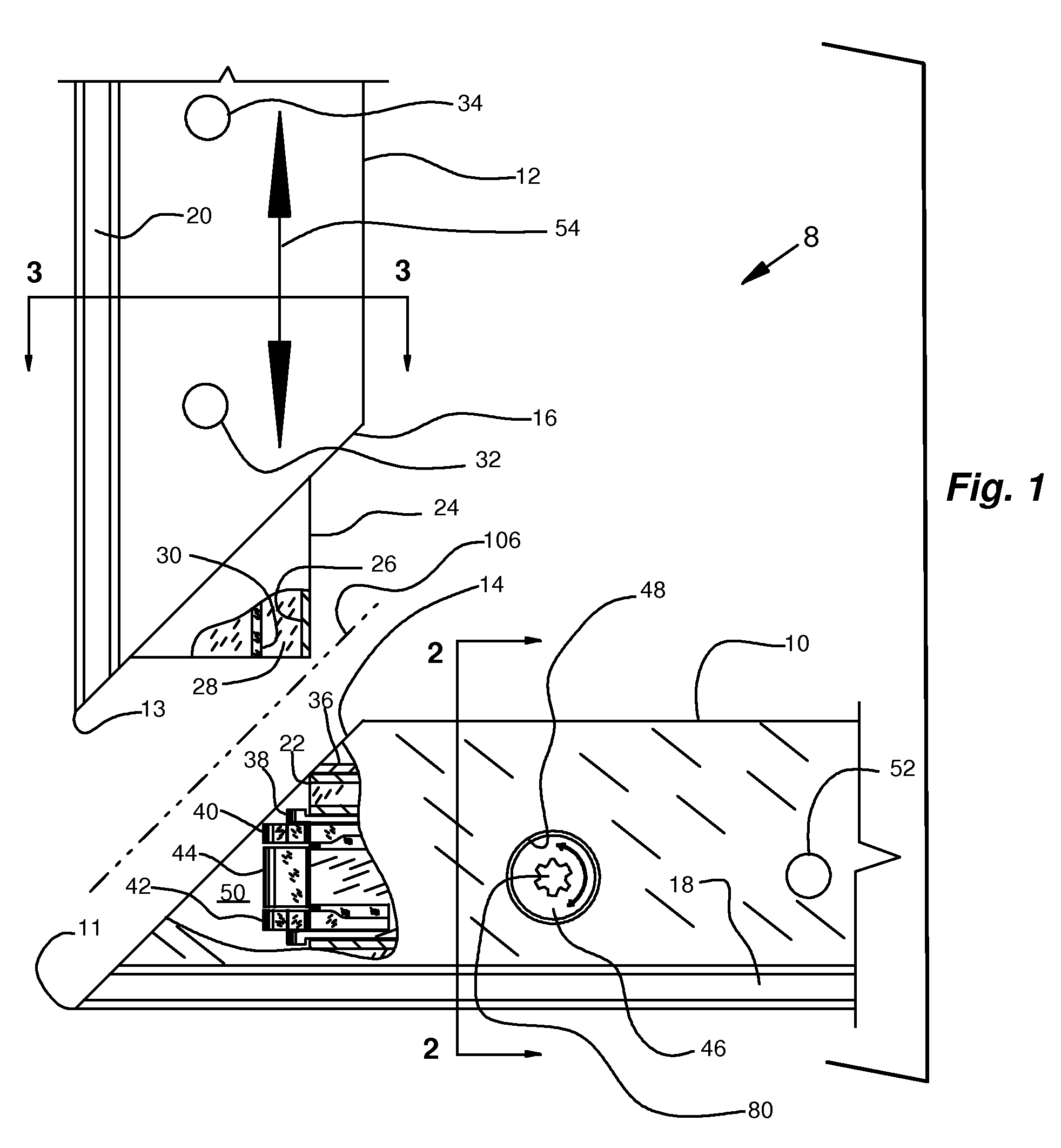
[0051]The following description of the best mode presently known generally relates to a system in which one quick release frame joint system holds two mating frame members in a strong, safe, rugged, and easily assembled and disassembled structural relationship.

[0052]With particular reference to the accompany drawings; in the embodiment of a frame joint system 8 illustrated in FIG. 1, a first frame member is indicated at 10 and a second frame member is indicated at 12 (see, for example, FIGS. 1-3, and 4). First beveled end 14 of first frame member 10 is beveled at approximately 45 degrees, and beveled first frame end 16 of second frame member 12 is likewise beveled at approximately 45 degrees. When these beveled ends are brought together, a 90 degree mitered joint is formed along joint plane 106. In the assembled configuration, first toe element 11 of first frame member 10 is in registry with second toe element 13 of second frame member 12 so that the laterally opening channels in th...


PUM


Abstract

A frame joint system including a first frame member and a second frame member. The frame members include laterally opening channels running axially thereof. The frame members are adapted to be rigidly secured together by quick release coupling. Embodiments of the frame joint system include mitered corner, end-to-face, face-to-face and end-to-end joints. The quick release coupling includes at least a first sleeve member and a gripping member. The gripping member is nested within the first sleeve member, and the first sleeve member is nested within the first frame member. The gripping member includes gripping elements that mate with a slot in a box rail element fixedly associated with the second frame member. Activating the gripping elements pulls the two frame members together into a rigid joint.

Description

RELATED APPLICATIONS[0001]This application claims the benefit of U.S. Provisional Application No. 61 / 152,213 filed Feb. 12, 2009 and U.S. Provisional Application No. 61 / 180,741 filed May 22, 2009, the content of each of which is incorporated by this reference in its entirety for all purposes as if fully set forth herein.TECHNICAL FIELD OF THE INVENTION[0002]The present invention relates generally to the field of display frame joints, particularly to quick disconnect frame joints that are useful in forming mitered corners, end-to-face joints, face-to-face joints and end-to-end joints in display frames.BACKGROUND OF THE INVENTION[0003]Frames, for example, display frames, generally comprise a series of generally straight frame members joined through mitered joints so as to form a closed figure such as a rectangle, or the like. The structural integrity of the frame depends on the rigidity and durability of the joints between the frame members. Previously, various expedients had been pro...

Claims


Application Information

Patent Timeline
Patent Type & Authority Patents(United States)
IPC IPC(8): F16B12/00A47G1/10
CPCA47G1/10Y10T403/7031Y10T403/4602Y10T403/555F16B2200/67F16B2200/65A47G1/101
Inventor FREY, ROBERT M.
Owner MOSS HLDG
Why Eureka
Try Eureka