Casing based on self-circulation oscillation jet, compressor and stability enhancing method thereof

A technology of oscillating jet flow and self-circulation, which is applied to components of pumping devices for elastic fluids, machines/engines, mechanical equipment, etc., and can solve problems such as poor safety, low reliability, and high reliability requirements

Pending Publication Date: 2020-10-23
AERO ENGINE ACAD OF CHINA
View PDF13 Cites 12 Cited by
  • Summary
  • Abstract
  • Description
  • Claims
  • Application Information

AI Technical Summary

Problems solved by technology

A large number of studies have shown that the use of unsteady-state disturbance can greatly improve the control efficiency of flow separation, but the working conditions in the aero-engine are harsh, and the reliability of all components is extremely high. The difficulty of using unsteady-state flow control lies in Lack of exciters with simple structure and high reliability
However, the unsteady-state flow control actuators used in the active control of compressors have defects such as poor safety, low reliability, and insufficient excitation strength.

Method used


Image

  • Casing based on self-circulation oscillation jet, compressor and stability enhancing method thereof
  • Casing based on self-circulation oscillation jet, compressor and stability enhancing method thereof
  • Casing based on self-circulation oscillation jet, compressor and stability enhancing method thereof

Examples


Embodiment 1

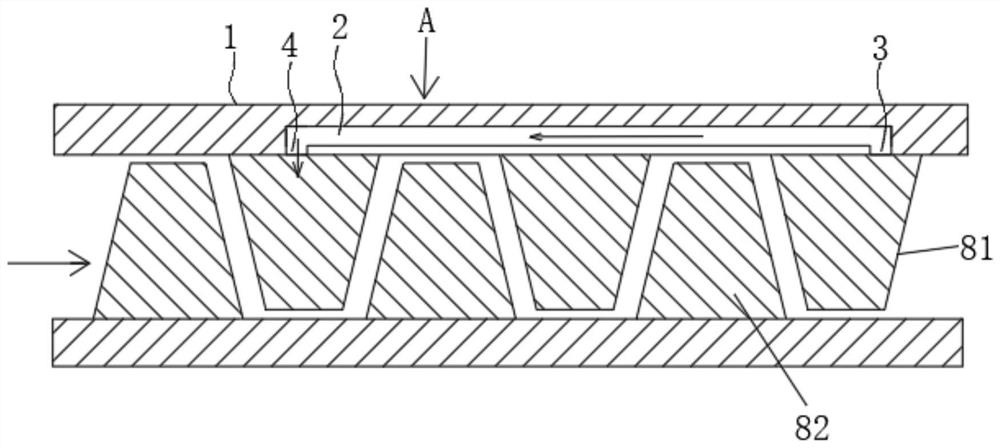
[0058] refer to figure 1 and figure 2 , a casing 1 based on a self-circulating oscillating jet, the casing 1 is provided with a fluid oscillator channel 2; in this embodiment, the fluid oscillator channel 2 adopts a pulse jet oscillator channel, Its characteristics are: it contains one import and two exports. Under steady-state inlet conditions, that is, when the inlet flow rate does not change, the main flow flows out alternately at the two outlets, and at each outlet, a pulsed jet is formed along the direction of the outlet channel.

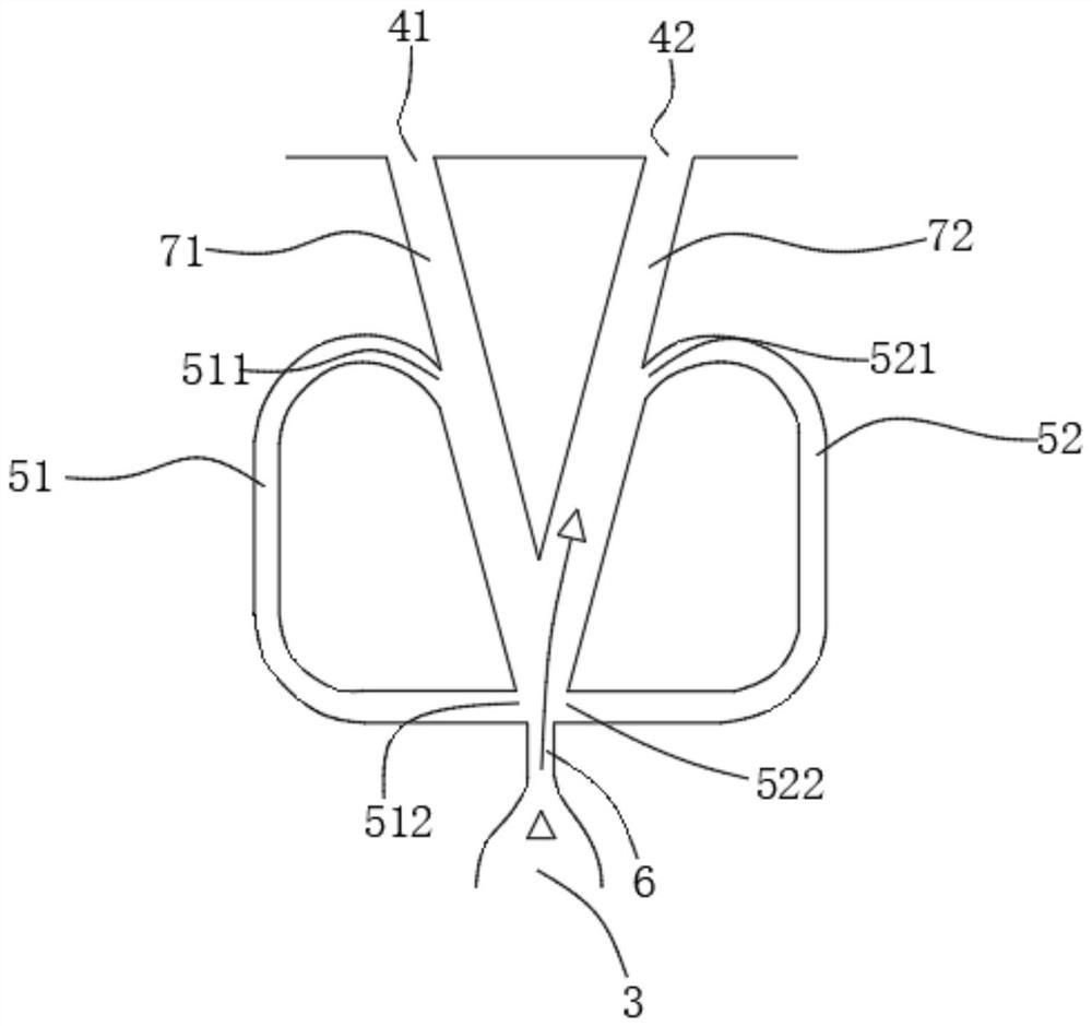
[0059] refer to figure 1 and figure 2 , the flow path 2 of the fluid oscillator in this embodiment includes: an oscillating jet bleed air inlet 3, an oscillating jet outlet 4, and a jet feedback for partly flowing from the oscillating jet bleed air inlet 3 to the oscillating jet outlet 4 The two feedback passages 5 return to the connecting portion between the oscillating jet bleed air inlet 3 and the oscillating jet outlet 4 .

[0060] r...

Embodiment 2

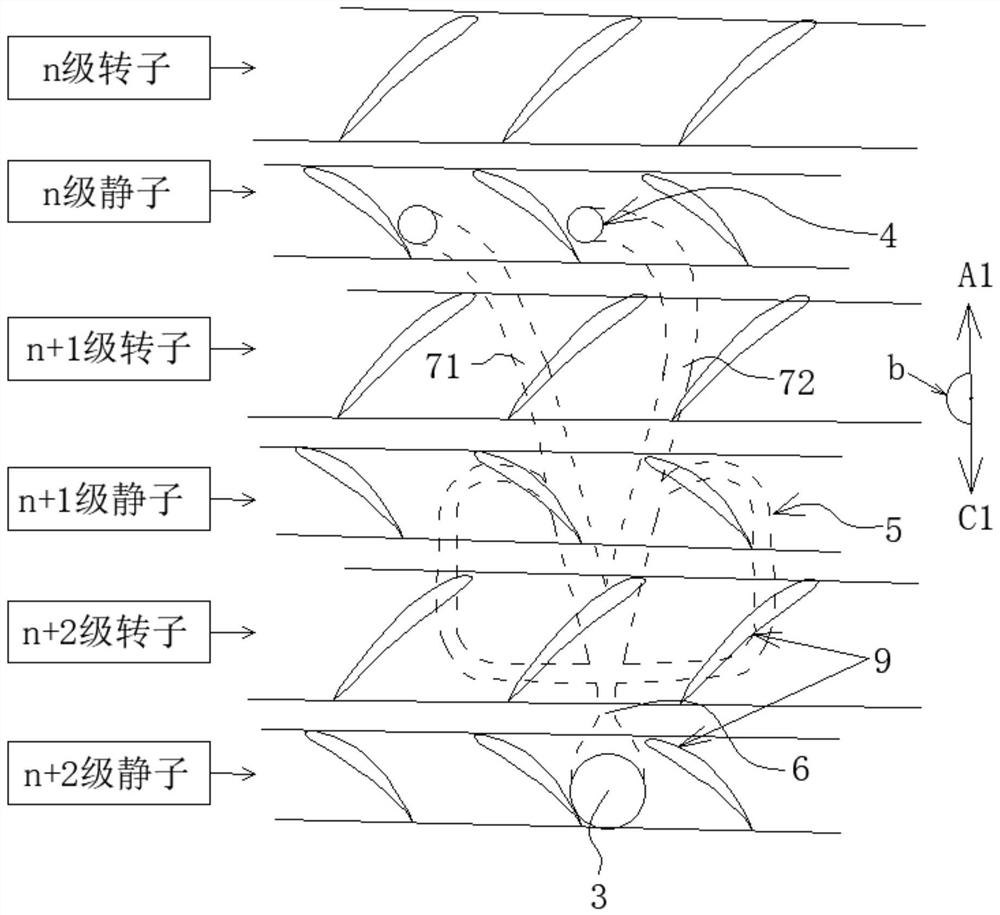
[0072] refer to Figure 7 , this embodiment is basically the same as Embodiment 1, the difference is that: the first oscillating jet outlet 41 and the second oscillating jet outlet 42 are respectively located on any two adjacent blades in the nth stage stator 81 of the compressor 9 The position in the flow channel, or the position within the axial projection range of any two adjacent rotor blades on the nth stage of the compressor on the casing. For example, refer to Figure 7 , the first oscillating jet outlet 41 is located at the top of any blade 9 of the nth stage stator 81 of the compressor, and the second oscillating jet outlet 42 is located at the top of any blade 9 of the nth stage rotor 82 of the compressor .

Embodiment 3

[0074] This embodiment is basically the same as Embodiment 1, and the fluid oscillator channel 2 adopts a pulse jet oscillator channel, refer to Figure 8 , the difference is that the outlet of the inlet air-introduction channel 6 of the fluid oscillator channel 2 communicates with a first feedback port 53 and a second feedback port 54; the first feedback port 53 passes through a The feedback channel 5 communicates with the second feedback port 54 .


PUM


Abstract

The invention provides a casing based on self-circulation oscillation jet, a compressor and a stability enhancing method thereof. A fluid oscillator flow channel is arranged in the casing, and air flow enters the fluid oscillator flow channel from an oscillation jet air entraining inlet between (n+m) stage stators or rotors of the casing; the pressure of the oscillation jet air entraining inlet is greater than the pressure of an oscillation jet outlet between n stage stators or rotors, the air flow forms oscillation jet on the oscillation jet outlet between the stators after flowing through the fluid oscillator flow channel, and angle area flow separation and suction surface flow separation corresponding to the top ends of stator blade grids are reduced; or, the oscillation jet isformed on the oscillation jet outlet of the rotors, tip clearance secondary flow corresponding to rotor blades is reduced, and the stable work margin of the compressor is improved; and due to a pressure difference, when the oscillation jet air entraining inlet is located between the (n+m) stage stators or rotors, the fluid oscillator flow channel generate suction action on a top end boundary layer and the secondary flow of the (n+m) stage stators or rotors, the flow separation is reduced, and the stability enhancing effect is generated.

Description

technical field [0001] The present disclosure relates to the treatment of the casing of the compressor, and in particular to a casing, a compressor and a stabilizing method thereof based on a self-circulating oscillating jet Background technique [0002] The main causes of compressor stall generally include the flow separation of the blade surface, the complex vortex action of the end wall and the corner area, etc. Passive or active flow control methods are used to suppress the flow separation of the blade surface, the leakage flow of the blade tip and the secondary flow. Flow and reducing the degree of flow blockage in the end area can improve the stability and efficiency of the compressor, thereby improving the overall performance of the compressor and expanding its stable working range and efficiency. In the prior art, by using the pressure difference between the front and rear stages of the compressor or between the suction surface and the pressure surface of the blade, ...

Claims


Application Information

Patent Timeline
Patent Type & Authority Applications(China)
IPC IPC(8): F04D29/54F04D29/00F02C7/00F02C3/04
CPCF04D29/542F04D29/544F02C3/04F02C7/00F04D29/002
Inventor 王士奇卢娟邵冬贾志刚
Owner AERO ENGINE ACAD OF CHINA
Why Eureka
Try Eureka