Fluid rectifying device

A rectifier and fluid technology, applied in the field of machinery, can solve problems such as unstable gas flow state

Active Publication Date: 2020-10-23
SGIS SONGSHAN CO LTD
View PDF4 Cites 0 Cited by
  • Summary
  • Abstract
  • Description
  • Claims
  • Application Information

AI Technical Summary

Problems solved by technology

The tail gas mainly comes from the tanks of the ammonia water system and the crude benzene system. The exhausted gas is mainly composed of water vapor and non-condensable (ammonia, benzene, etc.) gases. stable, resulting in an unstable gas flow state during the exhaust process

Method used


Image

  • Fluid rectifying device
  • Fluid rectifying device
  • Fluid rectifying device

Examples


Embodiment

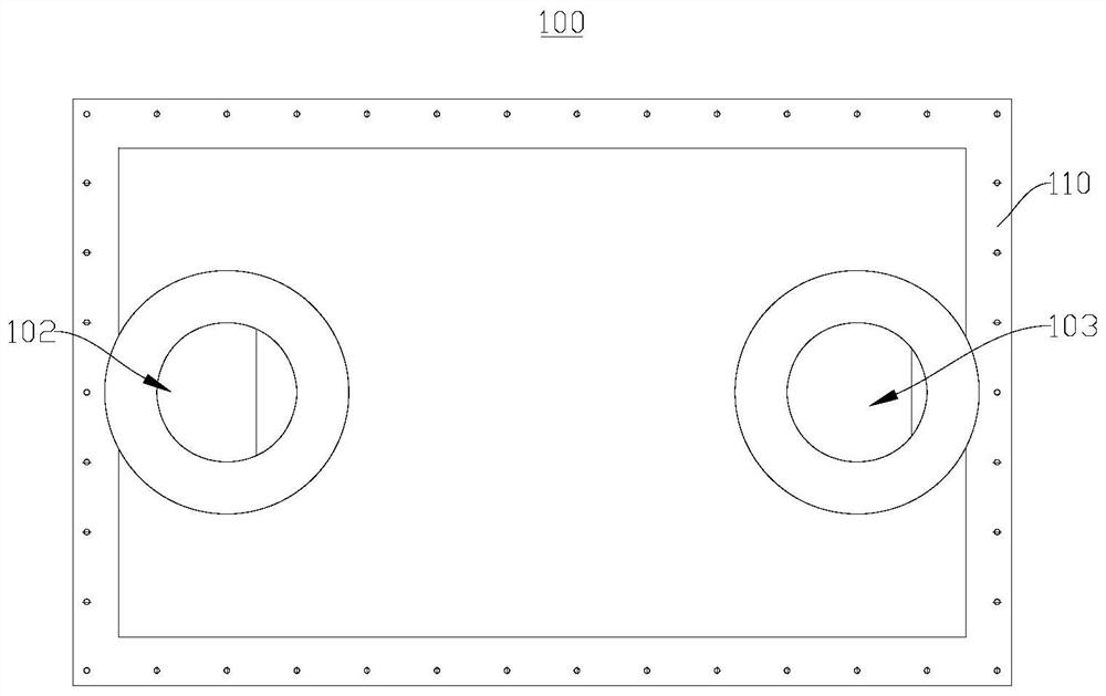
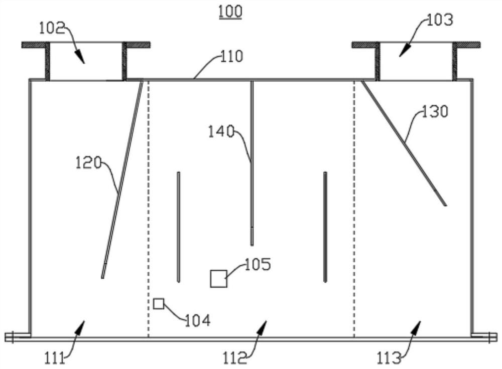
[0034] figure 1 A schematic structural view of the fluid rectification device 100 provided by the embodiment of the present application is shown, figure 2 It shows a schematic diagram of the internal structure of the fluid rectifying device 100 provided by the embodiment of the present application, please refer to figure 1 and figure 2 , in this embodiment, the external shape of the fluid rectification device 100 is approximately cylindrical, and correspondingly, the housing cavity 101 inside the fluid rectification device 100 is also approximately cylindrical. It should be noted that, in other embodiments of the present application The external shape of the fluid rectifying device 100 may be other shapes such as elliptical column, square column, etc. Correspondingly, the shape of the accommodating cavity 101 inside the fluid rectifying device 100 may also be other shapes. In the embodiment of the present application, the main function of the fluid rectification device 100...


PUM


Abstract

The application relates to the field of machinery, and in particular to a fluid rectifying device. The fluid rectifying device comprises a housing that is provided with an accommodating cavity, wherein the accommodating cavity comprises an inlet area, a middle area and an outlet area connected in sequence; the inlet area is provided with a first baffle, and the angle between the first baffle and the housing is 70-80 degrees; multiple partition plates are provided in the middle area and surround to form a reversing flow channel; the outlet area is provided with a second baffle, and the angle between the second baffle and the housing is 50-60 degrees. The setting of the first baffle can quickly rectify the fluid entering from the inlet and reduce its turbulence. The reversing flow channel inthe middle area adjusts the flow direction of the fluid many times to further reduce its degree of turbulence. The setting of the second baffle further rectifies the fluid flowing out of the middle area to reduce its degree of turbulence. The accommodating cavity also has the function of temporarily storing the fluid, which can make the fluid pressure at the outlet close to balance and reduce pressure fluctuations.

Description

technical field [0001] The present application relates to the mechanical field, in particular, to a fluid rectifying device. Background technique [0002] The tail gas produced by each equipment of the coking gas purification system is sent to the negative pressure gas pipeline in front of the gas blower through the pipeline, and the exhaust gas is remotely controlled by the automatic regulating valve on the tail gas pipeline. The tail gas mainly comes from the tanks of the ammonia water system and the crude benzene system, and the exhausted gas is mainly composed of water vapor and non-condensable (ammonia, benzene, etc.) gases. stable, resulting in an unstable gas flow state during the exhaust process. Contents of the invention [0003] The purpose of the embodiments of the present application is to provide a fluid rectifying device, which aims to provide a device capable of improving the fluid flow state. [0004] The application provides a fluid rectification device,...

Claims


Application Information

Patent Timeline
Patent Type & Authority Applications(China)
IPC IPC(8): F17D1/02F17D1/20F04D29/66
CPCF17D1/02F17D1/20F04D29/667
Inventor 杨涛杨志军王道元邹全荣周凌云吴冠雄李士军刘洋穆应东廖志均赵洪峰
Owner SGIS SONGSHAN CO LTD
Why Eureka
Try Eureka