

Target object identification method and device
A technology of target object and identification method, applied in the field of target object identification method and device, can solve the problems of poor reliability of identity information and the like
- Summary
- Abstract
- Description
- Claims
- Application Information
AI Technical Summary
Problems solved by technology
Method used
Image

Examples
Embodiment 1
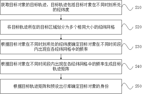
[0025] An embodiment of the present invention provides a target object recognition method, such as figure 1 shown, including:
[0026] Step S10: Obtain the target trajectory of the target object, the target trajectory includes the latitude and longitude of the target object at different times.
[0027]In a specific embodiment, the target object may be, for example, a pedestrian who needs to be identified. When obtaining the target trajectory of the target object, it is possible to obtain the trajectory within a longer period of time as much as possible. The longer the time period, the more obvious the law of the acquired target trajectory, and thus the easier it is to identify the target object.
[0028] In the embodiment of the present invention, the target trajectory includes the latitude and longitude of the target object at different times, because the trajectory at different times will interfere with the identification of the target object, so the target trajectory obta...
Embodiment 2
[0058] Embodiments of the present invention provide a target object recognition device, such as Figure 4 shown, including:
[0059] The trajectory acquisition module 10 is configured to acquire the target trajectory of the target object, the target trajectory includes the latitude and longitude of the target object at different times, for detailed description, see the description of step S10 in the first embodiment above.
[0060] The latitude and longitude grid determination module 20 is configured to divide the target area where the target trajectory is located into multiple latitude and longitude grids of the same size. For a detailed description, refer to the description of step S20 in the first embodiment above.
[0061] The frequency calculation module 30 is used to determine the frequency of the target object appearing in each latitude and longitude grid in different time periods according to the latitude and longitude of the target object at different times. For a det...
Embodiment 3
[0080] An embodiment of the present invention provides a computer device, such as Figure 7 As shown, the computer device mainly includes one or more processors 61 and memory 62, Figure 7 A processor 61 is taken as an example.
[0081] The computer device may also include: an input device 63 and an output device 64 .
[0082] Processor 61, memory 62, input device 63 and output device 64 can be connected by bus or other ways, Figure 7 Take connection via bus as an example.
[0083] The processor 61 may be a central processing unit (Central Processing Unit, CPU). The processor 61 may also be other general-purpose processors, digital signal processors (Digital Signal Processor, DSP), application specific integrated circuits (Application Specific Integrated Circuit, ASIC), field-programmable gate arrays (Field-Programmable Gate Array, FPGA) or Other chips such as programmable logic devices, discrete gate or transistor logic devices, discrete hardware components, or combinati...
PUM
 Abstract
Description
Claims
Application Information