
High-voltage vacuum circuit breaker

A vacuum circuit breaker and high-voltage technology, which is applied in high-voltage air circuit breakers, high-voltage/high-current switches, circuits, etc., can solve problems such as broken copper sheets, short external insulation distance, and difficult replacement

Pending Publication Date: 2020-10-23
苏州兰姆达电气有限公司
View PDF0 Cites 4 Cited by
  • Summary
  • Abstract
  • Description
  • Claims
  • Application Information

AI Technical Summary

Problems solved by technology

[0003] However, in the existing high-voltage vacuum circuit breakers, the moving end of the arc extinguishing chamber and the outlet column of the moving end are generally connected through a soft connection. After the moving contact moves back and forth for a certain number of times in this connection, the copper part of the middle soft connection Chips are prone to breakage, resulting in a reduction in the current carrying capacity of the primary circuit. If broken copper pieces fall into the wall of the solid-sealed pole, it is easy to cause relative ground discharge
In addition, the existing insulating bracket still has disadvantages such as inconvenient installation, short external insulation distance, inconvenient adjustment of the opening spring structure of the existing chassis frame, and difficulty in replacement.

Method used


Image

  • High-voltage vacuum circuit breaker
  • High-voltage vacuum circuit breaker
  • High-voltage vacuum circuit breaker

Examples


Embodiment Construction

[0044] The preferred embodiments of the present invention will be described in detail below in conjunction with the accompanying drawings.

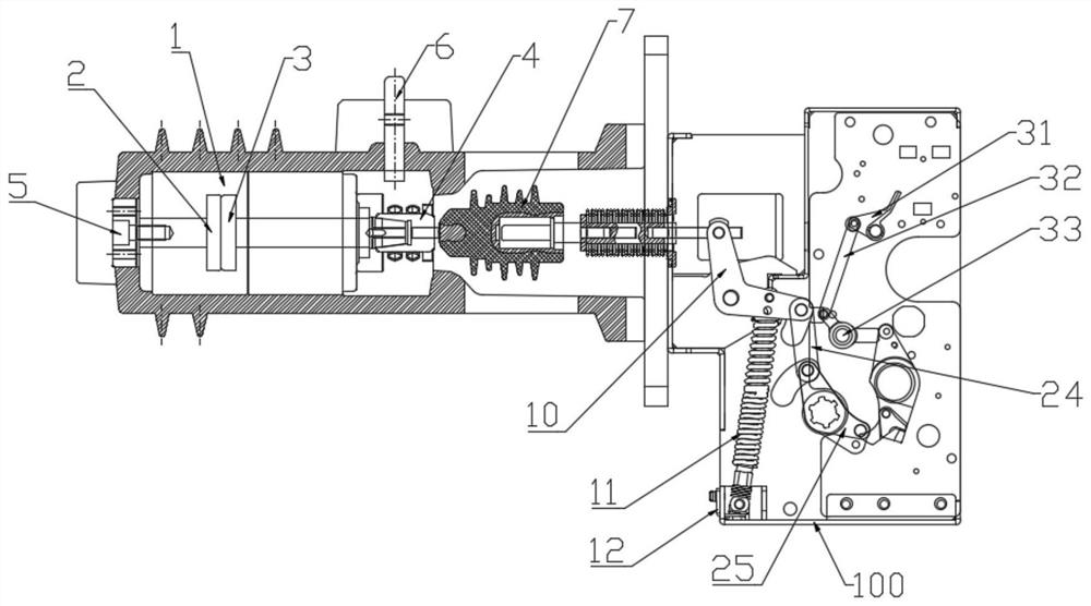
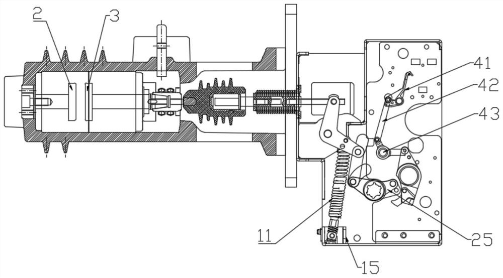
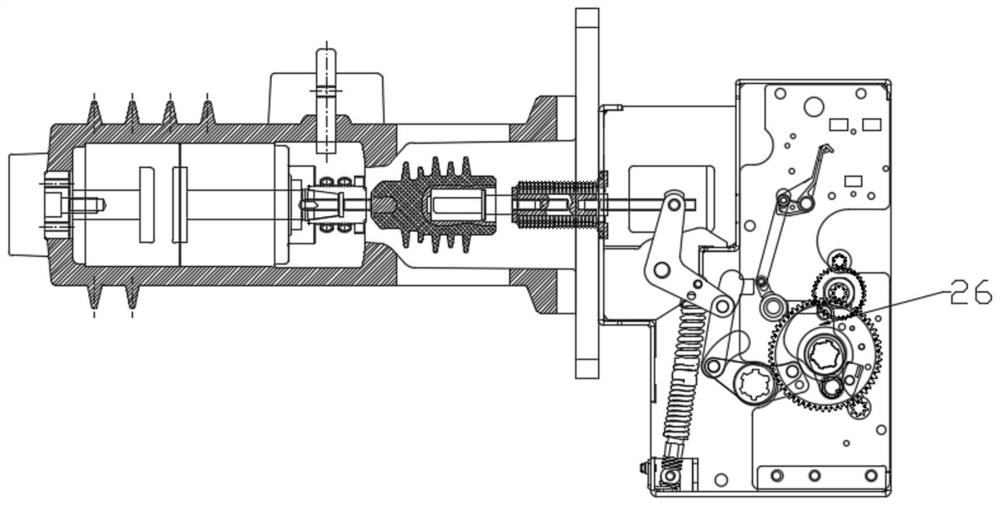
[0045] refer to Figure 1-7 , is a high-voltage vacuum circuit breaker according to the present invention, including a box support 100 and a contact system, an arc extinguishing system and an operating mechanism arranged on the box support.

[0046] The arc extinguishing system includes a vacuum interrupter 1 and an arc extinguishing structure inside it. The contact system includes a static contact 2 and a moving contact 3 inside the vacuum interrupter 1. The outer end of the static contact 2 is electrically Connect the copper outlet 5 at the static end, and the outer end of the moving contact 3 is electrically connected to the copper outlet 6 at the moving end.

[0047] The operating mechanism includes an insulating pull rod 7, a large crank arm 10, an opening spring 11, an opening operation component and a closing operation component, ...


PUM


Abstract

The invention discloses a high-voltage vacuum circuit breaker. The high-voltage vacuum circuit breaker comprises a box body support, a contact system, an arc extinguishing system and an operating mechanism, wherein the contact system, the arc extinguishing system and the operating mechanism are arranged on the box body support, the arc extinguishing system comprises a vacuum arc extinguishing chamber, the contact system comprises a static contact and a moving contact which are arranged in the vacuum arc extinguishing chamber, the operating mechanism comprises an insulating pull rod which is fixedly connected with the moving contact, an end, close to the exterior of the moving contact, of the insulating pull rod is fixedly sleeved with a conductive column electrically connected with the moving contact, the periphery of the conductive column is sleeved with a moving-end copper outgoing line connecting piece, an inner end of the moving-end copper outgoing line is fixed on the moving-end copper outgoing line connecting piece, an annular installation groove is formed in an inner wall of the movable end copper outgoing line connecting piece, an elastic annular sliding contact finger is fixedly installed in the installation groove, the sliding contact finger partially stretches out of the surface of the inner wall of the movable end copper outgoing line connecting piece, and the outerside surface of the conductive column makes elastic and sliding contact with the part, stretching out of the inner wall of the movable end copper outgoing line connecting piece, of the sliding contact finger. The circuit breaker is advantaged in that the circuit breaker is stable and reliable in connection, good in conductivity, convenient to install and good in insulating property.

Description

technical field [0001] The invention relates to a circuit breaker, in particular to a high-voltage vacuum circuit breaker. Background technique [0002] A circuit breaker refers to a switching device that can close, carry and break current under normal circuit conditions, and can close, carry and break current under abnormal circuit conditions (including short-circuit conditions) within a specified time. Circuit breakers can be used to distribute electric energy, start asynchronous motors infrequently, protect power lines and motors, and automatically cut off the circuit when they are severely overloaded, short-circuited, or under-voltage. Its function is equivalent to a fuse-type switch. Combination with overheating and underheating relays, etc. Moreover, there is generally no need to change parts after breaking the fault current. At present, it has been widely used. [0003] However, in the existing high-voltage vacuum circuit breakers, the moving end of the arc extingu...

Claims


Application Information

Patent Timeline
IPC IPC(8): H01H33/66H01H33/664H01H33/666
CPCH01H33/6606H01H33/664H01H33/666
Inventor 不公告发明人
Owner 苏州兰姆达电气有限公司
Learn More