Micro circuit breaker

A technology of miniature circuit breakers and bimetals, applied in circuit breaker parts, circuit breaker contacts, protection switch operation/release mechanisms, etc., can solve the problems of virtual welding, temperature rise at solder joints, and high production costs

Pending Publication Date: 2020-10-23
浙江友路电气有限公司
View PDF0 Cites 0 Cited by
  • Summary
  • Abstract
  • Description
  • Claims
  • Application Information

AI Technical Summary

Problems solved by technology

[0004] Therefore, the technical problem to be solved by the present invention is to overcome the defects in the prior art that the moving contact and the flexible conductive member are connected by welding, resulting in high production cost, virtual welding, and temperature rise at the solder joint, thereby providing A small circuit breaker with low production cost and high reliability

Method used


Image

  • Micro circuit breaker
  • Micro circuit breaker
  • Micro circuit breaker

Examples


Embodiment

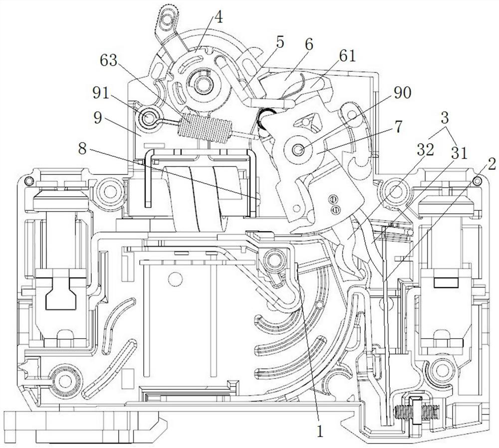
[0035] This embodiment provides a small circuit breaker, including a contact mechanism, an operating mechanism, an electromagnetic trip mechanism, and a thermal trip mechanism.

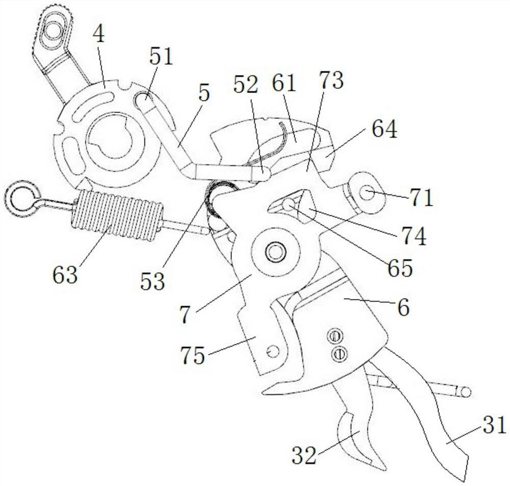
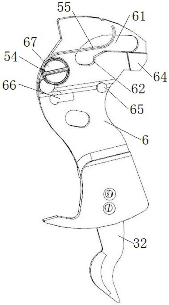
[0036] contacts, such as figure 1 and 6As shown, it includes a static contact 1 and a moving contact plate 32 opposite to the static contact 1. The moving contact plate 32 is connected to the bimetal 2 of the thermal tripping mechanism through a flexible conductive segment 31. In this embodiment , the flexible conductive section 31 is integrally connected with the moving contact plate 32, and the moving contact plate 32 is extruded into a plate shape by a part of the same flexible conductor where the flexible conductive section 31 is located, that is, the flexible conductor One part is used to be pressed into the moving contact plate 32, and the other part is used to directly connect with the bimetal sheet, and the flexible conductor is a copper braid or copper flexible stranded wire.

[0037] The ...


PUM


Abstract

The invention provides a micro circuit breaker. The micro circuit breaker comprises a conductive part which is arranged between a static contact and a bimetallic strip and can be connected with the static contact and the bimetallic strip, the conductive part is provided with a flexible conductive section which can be connected with the bimetallic strip and a moving contact plate which is integrally connected with the flexible conductive section, and the moving contact plate is formed into a plate shape by pressing one part of the same flexible conductor where the flexible conductive section islocated. Namely, one part of the flexible conductor is used for being pressed into a moving contact plate, and the other part is directly connected with a bimetallic strip. The micro circuit breakeris advantaged in that compared with the mode that in the prior art, the moving contact is stamped on the copper plate firstly, then the moving contact is connected with the flexible conductive part ina welded mode, the processing procedure is simpler, production cost is reduced, defects of pseudo soldering, high temperature rise and the like caused by welding are overcome, reliability is higher,and the service life is prolonged.

Description

technical field [0001] The invention relates to the technical field of circuit breakers, in particular to a small circuit breaker. Background technique [0002] Miniature circuit breakers refer to protective appliances installed on terminal distribution lines, which are mainly used for overload and short-circuit protection of lines and electrical equipment. [0003] The contact mechanism of the existing miniature circuit breaker includes a moving contact 01 arranged on the contact bracket 04, and a static contact arranged opposite to the moving contact 01. The moving contact 01 rotates in conjunction with the contact bracket 04, thereby The static contacts are connected or disconnected, such as Figure 7 As shown, the moving contact 01 is connected to the bimetal sheet 03 through the flexible conductive part 02. At present, the moving contact 01 is stamped and formed by copper plate, and the flexible conductive part 02 is generally a copper braid or copper flexible stranded ...

Claims


Application Information

Patent Timeline
Patent Type & Authority Applications(China)
IPC IPC(8): H01H71/16H01H71/40H01H71/12H01H73/04
CPCH01H71/12H01H71/16H01H71/40H01H73/04
Inventor 周红兵
Owner 浙江友路电气有限公司
Why Eureka
Try Eureka