Crimp contact

A contact and crimping connection technology, which is applied in the direction of contact manufacturing, connecting contact materials, connecting device parts, etc., can solve problems such as unsatisfactory crimping connections

Pending Publication Date: 2020-10-23
TE CONNECTIVITY GERMANY GMBH
View PDF2 Cites 1 Cited by
  • Summary
  • Abstract
  • Description
  • Claims
  • Application Information

AI Technical Summary

Problems solved by technology

However, it can happen that the upper edge slips on the inside of the crimp flank and, as a result, produces an unsatisfactory crimp connection

Method used


Image

  • Crimp contact
  • Crimp contact
  • Crimp contact

Examples


Embodiment Construction

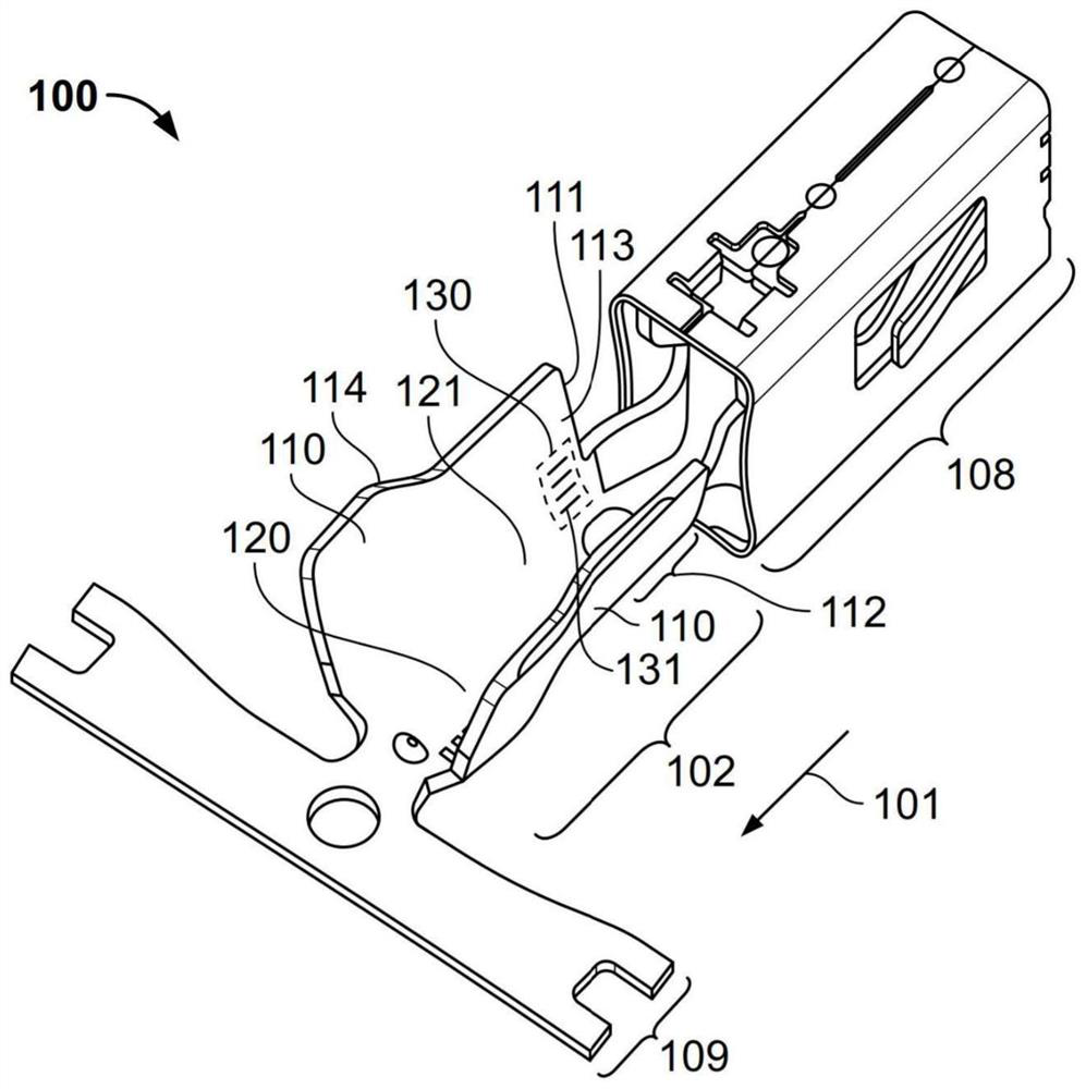
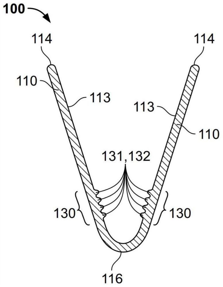
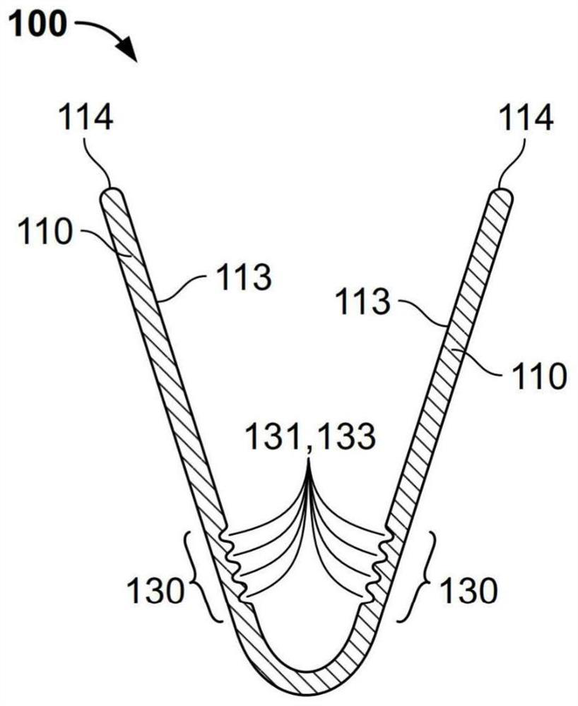
[0040] figure 1 A crimp contact 100 is shown, which is suitable for crimping figure 1 conductors not shown. The crimping contact 100 has at least one crimping side 110 which can be crimped. figure 1 Two such crimp sides 110 are shown in . In this case, the crimp side 110 serves to surround the conductor after crimping. The crimp contact 100 also has a receptacle 120 for the conductor, which extends in the longitudinal direction 101 of the crimp contact 100 as far as the receiving end 121 . The crimp side 110 extends on the receiving end 121 in the longitudinal direction 101 to the front end 111 . The front region 112 of the crimp contact 100 is arranged between the receiving end 121 and the front end 111 . In the front region 112 of the crimp contact 100 it has a structured region 130 .

[0041] figure 1 The two crimping sides 110 are shown forming a crimping sleeve 102 into which a conductor can be inserted before crimping. Furthermore, the crimp contact 100 has a con...


PUM

PropertyMeasurementUnit
thicknessaaaaaaaaaa
thicknessaaaaaaaaaa
heightaaaaaaaaaa

Abstract

The invention relates to a crimp contact for crimping a conductor having a crimpable crimp flank for enclosing the conductor after crimping, and a receptacle for the conductor, which receptacle extends in a longitudinal direction of the crimp contact up to a receiving end. The crimp flank extends in the longitudinal direction over the receiving end up to a front end, with a front region of the crimp contact being arranged between the receiving end and the front end. The crimp contact has at least one structured region in the front region.

Description

technical field [0001] The invention relates to a crimp contact for crimping conductors, a method for producing such a crimp contact, and a crimp connection. Background technique [0002] Crimp contacts are known from the prior art. These usually have two crimp sides arranged on either side of the crimp back. When the crimp contact is contacted by the conductor end, the conductor end is positioned between the crimp sides and above the crimp back. Then, using crimping pliers or a crimping tool, for example, bend the crimp side around the end of the conductor. During this crimping process, the conductors are mechanically and electrically connected to the crimped contacts. Such a crimp contact is disclosed, for example, in the printed document DE 10 2015 224 219 A1. [0003] During crimping, the upper edge of the crimp side hits the inside of the crimp side. The crimped sides can then be rolled up and in this way assume a helical shape after crimping. However, it can happ...

Claims


Application Information

Patent Timeline
Patent Type & Authority Applications(China)
IPC IPC(8): H01R4/18H01R43/048
CPCH01R4/184H01R4/188H01R43/048H01R4/62H01R13/5216H01R43/16H01R2201/26H01R4/18H01R4/185
Inventor J.布朗特U.布鲁梅尔S.萨克斯
Owner TE CONNECTIVITY GERMANY GMBH
Why Eureka
Try Eureka