AI technical title is built by Patsnap AI team. It summarizes the technical point description of the patent document.
A technology for automatic assembly and charging of plugs, applied in the assembly/disassembly of contacts, etc., which can solve the problems that the plug is not easy to stand on the desktop, the degree of automation is high, and the work is cumbersome.
Inactive Publication Date: 2020-10-23
长兴梦晨节能设备有限公司
View PDF0 Cites 3 Cited by
Summary
Abstract
Description
Claims
Application Information
AI Technical Summary
This helps you quickly interpret patents by identifying the three key elements:
Problems solved by technology
Method used
Benefits of technology
Problems solved by technology
[0005] The purpose of the present invention is to address the deficiencies of the prior art. By setting up a finished product discharge mechanism, the finished charger after the assembly is seamlessly arranged and then extracted under the drive of the switching component and automatically transferred to the plug. Facing upwards, it is automatically pushed out by the arrangement components. Its work output has a high degree of automation, and it is conducive to the output of groups of finished chargers one by one, thus solving the problem that the plug is not easy to stand on the table and needs to be turned manually. Placing the housing on the table will cause cumbersome work and poor automation
Method used
Image
Click on the blue label to locate the original text in one second.
Reading with bidirectional positioning of images and text.
Examples
Embodiment 1
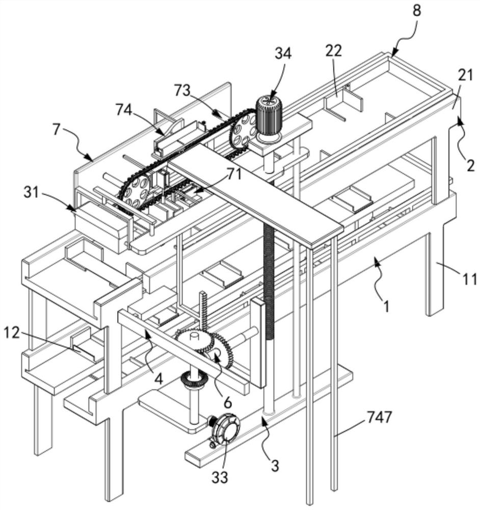
[0076] Such as figure 1 with figure 2 As shown, a charging plug automatic assembly device, including:
[0077] A plug transmission mechanism 1, the plug transmission mechanism 1 includes a transmission track a11 and several sets of receiving plates a12 that are equidistantly matched and slidably arranged on the transmission track a11, and the receiving plates a12 are set to match the shape of the plug 10;
[0078] The housing transmission mechanism 2, the housing transmission mechanism 2 is arranged above the plug transmission mechanism 1, and includes a transmission track b21 and several groups of receiving plates b22 that are matched and slidably arranged on the transmission track b21 at equal intervals, the The receiving plate b22 is arranged to match the shape of the housing 20;
[0079] An automatic assembly mechanism 3, the automatic assembly mechanism 3 is located at the assembly station, and the automatic assembly mechanism 3 includes a first adsorption assembly 31 ...
Embodiment 2
[0125] Such as Figure 20 , Figure 21 As shown, the components that are the same as or corresponding to those in the first embodiment are marked with the corresponding reference numerals in the first embodiment. For the sake of simplicity, only the differences from the first embodiment will be described below. The difference between this embodiment two and embodiment one is:
[0126] further, such as Figure 20 , Figure 21 As shown, the flat pushing assembly 4 includes:
[0127] A flat plate 41, the flat plate 41 is matched and engaged in the transmission track b21;
[0128] A connecting frame 42, the connecting frame 42 is fixedly connected with the moving end of the flat plate 41; and
[0129] The limiting track 43 is provided with a telescopic unit b44 inside the limiting track 43 , and the telescopic unit b44 is fixedly connected with the connecting frame 42 .
[0130] In this embodiment, by setting the horizontal pushing assembly 4 to cooperate with the first tran...
PUM
Abstract
The invention relates to an automatic charging plug assembling device. The device comprises: a plug transmission mechanism which comprises a transmission track a and a bearing plate a; a shell transmission mechanism which is arranged above the plug transmission mechanism and comprises a transmission track b and a bearing plate b; an automatic assembling mechanism which is located at the assemblingstation and comprises a first adsorption assembly, a second adsorption assembly, a vacuum pump and a lifting assembly, wherein a horizontal pushing assembly is arranged on the assembling station andis in synchronous transmission with the lifting assembly through a first transmission part; and a finished product discharging mechanism which comprises a stripping assembly, a control assembly, a switching assembly and an arrangement assembly, wherein a driving mechanism intermittently and synchronously moves the bearing plate a and the bearing plate b towards the output end of the shell transmission mechanism. The technical problems that a plug is not easy to stand on a table top, a shell needs to be placed on the table top through manual overturning, the work is tedious, and the automationdegree is poor are solved.
Description
technical field [0001] The invention relates to the technical field of charging plugs, in particular to an automatic assembly device for charging plugs. Background technique [0002] At present, in the production process of chargers, the assembly equipment and testing equipment are distributed discretely. Through workers' loading and unloading and manual handling, the degree of automation is low, the production capacity is low, and there are obvious deficiencies. With the continuous development of the industry, the labor cost continues to increase. The emergence of labor and recruitment difficulties has made the labor cost of enterprises account for an increasing proportion of the company's cost, and the development of automation is becoming more and more important. [0003] The patent document with the patent number CN2017216386504 discloses a kind of assembly equipment for charger production, including a support seat, one end of the upper surface of the support seat is pro...
Claims
Application Information
Patent Timeline
Application Date:The date an application was filed.
Publication Date:The date a patent or application was officially published.
First Publication Date:The earliest publication date of a patent with the same application number.
Issue Date:Publication date of the patent grant document.
PCT Entry Date:The Entry date of PCT National Phase.
Estimated Expiry Date:The statutory expiry date of a patent right according to the Patent Law, and it is the longest term of protection that the patent right can achieve without the termination of the patent right due to other reasons(Term extension factor has been taken into account ).
Invalid Date:Actual expiry date is based on effective date or publication date of legal transaction data of invalid patent.

