
Mold box overturning and lifting device for aerated concrete plate production

A technology for the production of air-entrained concrete and slabs, which can be applied to unloading devices, molds, manufacturing tools, etc., and can solve the problems of affecting the turning process, production pollution, and resource consumption.

Pending Publication Date: 2020-10-27
DONGYUE MACHINERY GRP
View PDF0 Cites 1 Cited by
  • Summary
  • Abstract
  • Description
  • Claims
  • Application Information

AI Technical Summary

Problems solved by technology

[0002] Since the 21st century, as the world attaches great importance to resources and the environment, people have put forward higher requirements for building materials. Traditional sintered red brick factories are being gradually shut down due to large production pollution and serious resource consumption. In order to meet The current building needs, aerated panels came into being. As a new type of building material, it has many advantages that traditional building materials do not have: energy saving and light weight, shockproof, sound insulation and warmth. , it is necessary to complete the opening and closing action of the mold to demould the green body. During the turning process, the fixing of the mold box axis is particularly important. Its fixing directly affects the entire turning process, thus affecting the quality of the green body after demoulding , while the traditional locking mode needs to be driven by an oil cylinder for locking, there is a risk of falling off, and the cost is high. Therefore, a mold box flipping and lifting device for the production of aerated concrete slabs is proposed.

Method used


Image

  • Mold box overturning and lifting device for aerated concrete plate production
  • Mold box overturning and lifting device for aerated concrete plate production
  • Mold box overturning and lifting device for aerated concrete plate production

Examples


Embodiment Construction

[0017] The following will clearly and completely describe the technical solutions in the embodiments of the present invention with reference to the accompanying drawings in the embodiments of the present invention. Obviously, the described embodiments are only some, not all, embodiments of the present invention.

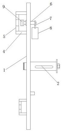
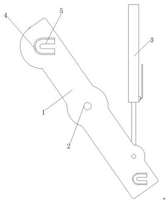
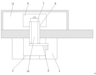
[0018] refer to Figure 1-4 , a mold box turning and lifting device for the production of aerated concrete slabs, including a turning plate 1, an installation shaft 2 is fixed at the middle position of the side wall of the turning plate 1, and a U-shaped bending plate 4 is welded on one end of the side wall of the turning plate 1. For the existing mold box shaft, adjust the position of the installation shaft 2, and weld other parts on it as required, determine the shape of the U-shaped bending plate 4, and strengthen the turning plate 1 according to the stress-bearing part, and the inner side of the U-shaped bending plate 4 is far away from the The U-shaped block 5 i...


PUM


Abstract

The invention discloses a mold box overturning and lifting device for aerated concrete plate production. The mold box overturning and lifting device for aerated concrete plate production comprises anoverturning plate, a mounting shaft is fixedly arranged on the middle of the side wall of the overturning plate, one end of the side wall of the overturning plate is welded with a U-shaped bent plate,one side, away from the overturning plate, of the inner side of the U-shaped bent plate is welded with U-shaped block, a gravity self-locking mechanism is arranged at a position, close to the U-shaped bent plate, of the side wall of the overturning plate, a hydraulic telescopic oil cylinder is rotationally connected to one end, away from the U-shaped block, of the side wall of the overturning plate, the gravity self-locking mechanism comprises a round hole formed in the position, close to the U-shaped bent plate, of the overturning plate, a shaft sleeve is arranged into the round hole in an inserted mode, a rotating shaft is rotationally connected to the inner wall of the shaft sleeve, a rotating arm is fixedly arranged on one end, away from the U-shaped block, of the rotating shaft through a bolt, a configuration block is fixedly arranged on one end of the rotating arm, and a self-locking hook is arranged at one end, away from the rotating arm, of the rotating shaft. According to themold box overturning and lifting device for aerated concrete plate production, protection can be carried out, the configuration block is prevented from being influenced by the outside, the reliability is higher, the structure is simple, and the equipment manufacturing cost is greatly reduced.

Description

technical field [0001] The invention relates to the technical field of aerated concrete molding, in particular to a mold box turning and lifting device for production of aerated concrete slabs. Background technique [0002] Since the 21st century, as the world attaches great importance to resources and the environment, people have put forward higher requirements for building materials. Traditional sintered red brick factories are being gradually shut down due to large production pollution and serious resource consumption. In order to meet The current building needs, aerated panels came into being. As a new type of building material, it has many advantages that traditional building materials do not have: energy saving and light weight, shockproof, sound insulation and warmth. , it is necessary to complete the opening and closing action of the mold to demould the green body. During the turning process, the fixing of the mold box axis is particularly important. Its fixing direc...

Claims


Application Information

Patent Timeline
IPC IPC(8): B28B13/06B28B7/08
CPCB28B7/087B28B13/06
Inventor 孙京伟高兴鹏马骏
Owner DONGYUE MACHINERY GRP
Learn More