The positioning structure of the mold

A positioning structure and mold technology, applied in the coating and other directions, can solve the problems of product size not meeting production requirements, wear of positioning column 110, non-compliance with production requirements, etc., to save mold opening time, reduce manufacturing costs, and simplify manufacturing Effect

Active Publication Date: 2022-03-15
MITAC PRECISION TECH(KUNSHAN) CORP
View PDF0 Cites 0 Cited by
  • Summary
  • Abstract
  • Description
  • Claims
  • Application Information

AI Technical Summary

Problems solved by technology

However, when the mold is clamped, the core of the female mold repeatedly presses down on the positioning pin, which will cause wear on the outside of the positioning pin 110. If things go on like this, the diameter of the positioning pin 110 will become smaller and smaller. The smaller the diameter of the positioning pin 110, the smaller the diameter of the positioning pin 110. Loose, and even lead to the size of the final molded product does not meet the production requirements
[0003] In view of this, it is necessary to provide a positioning structure of the mold, which is used to fix the metal parts and prevent the metal parts from moving during injection molding, resulting in the molded products not meeting the production requirements

Method used


Image

  • The positioning structure of the mold
  • The positioning structure of the mold
  • The positioning structure of the mold

Examples


Embodiment Construction

[0019] In order to further illustrate the technical means and effects adopted by the present invention, a detailed description will be given below in conjunction with a preferred embodiment of the present invention and its accompanying drawings.

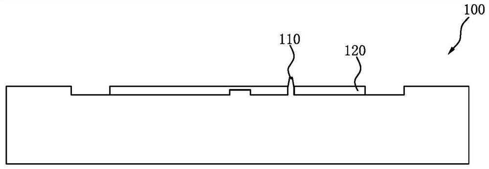
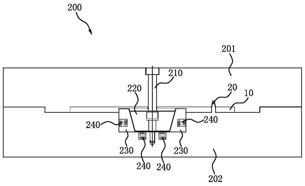
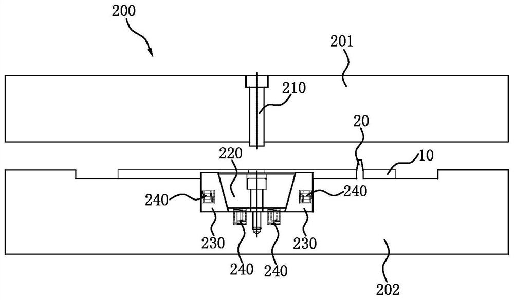
[0020] see figure 2 , figure 2 It is a structural schematic diagram of the positioning structure of the mold of the present invention in the mold clamping state. In this embodiment, the positioning structure 200 of a mold provided by the present invention is set in a mold for embedding plastic parts in metal parts 10, and the mold includes a female mold core 201, a male mold core 202 and a positioning column 20. The positioning structure 200 of the mold includes:

[0021] Ejector pin 210, which is arranged on the bottom surface of the female mold core 201;

[0022] A shifting block 220, which is arranged in the male mold core 202 and is located below the push rod 210;

[0023] Two positioning blocks 230, which are arranged in t...


PUM


Abstract

The invention discloses a positioning structure of a mold, which is arranged in a mold for embedding plastic parts in metal parts. The mold includes a female mold core, a male mold core and a positioning column. The positioning structure of the mold includes: a push rod, It is set on the bottom surface of the female mold core; a shift block is set in the male mold core and is located below the ejector rod; two positioning blocks are set in the male mold core, and the two positioning blocks are respectively Located on both sides of the shifting block, the shifting block slides up and down between the two positioning blocks, one of the positioning blocks is at a certain distance from the metal part; elastic elements are respectively arranged on the male mold core and the metal part Between the shifting block and the positioning block, the elastic element pushes the shifting block and the positioning block to move through elastic deformation. The positioning structure of the mold of the present invention, through the cooperation between the ejector rod, the shifting block, the positioning block and the elastic element, can prevent the metal parts from forming failure caused by sliding during forming.

Description

【Technical field】 [0001] The invention relates to a positioning structure, in particular to a positioning structure of a mold. 【Background technique】 [0002] see figure 1 , figure 1 A schematic diagram of a mold structure for embedding plastic parts in metal parts is shown. The mold 100 has a positioning column 110. When molding, the metal piece 120 is first put into the positioning column 110. When the mold is closed, the female mold core presses the metal piece 120 downward, and then injection molding. However, when the mold is clamped, the core of the female mold repeatedly presses down on the positioning pin, which will cause wear on the outside of the positioning pin 110. If things go on like this, the diameter of the positioning pin 110 will become smaller and smaller. The smaller the diameter of the positioning pin 110, the smaller the diameter of the positioning pin 110. Loose, and even lead to the size of the final molded product does not meet the production req...

Claims


Application Information

Patent Timeline
Patent Type & Authority Patents(China)
IPC IPC(8): B29C45/14B29C45/40
CPCB29C45/14065B29C45/4005B29C2045/14163
Inventor 夏凤兵
Owner MITAC PRECISION TECH(KUNSHAN) CORP
Why Eureka
Try Eureka