
Equipment for winding paper cups into cylinders

A technology of forming a tube and equipment, which is applied in the manufacture of papermaking, paper/cardboard containers, rigid/semi-rigid containers, etc., and can solve the problems of unfavorable mass production and slow speed.

Inactive Publication Date: 2020-10-27
梁闰强
View PDF11 Cites 0 Cited by
  • Summary
  • Abstract
  • Description
  • Claims
  • Application Information

AI Technical Summary

Problems solved by technology

[0005] In order to overcome the shortcomings of the manual method of rolling cardboard into a tube, the process of rolling cardboard into a tube is slow and unfavorable for mass production, the technical problem of the present invention is to provide a method that can sequentially unload the cardboard, and A device that can quickly roll cardboard into a tube and roll a paper cup into a tube

Method used

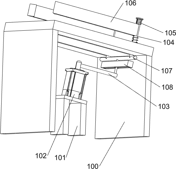
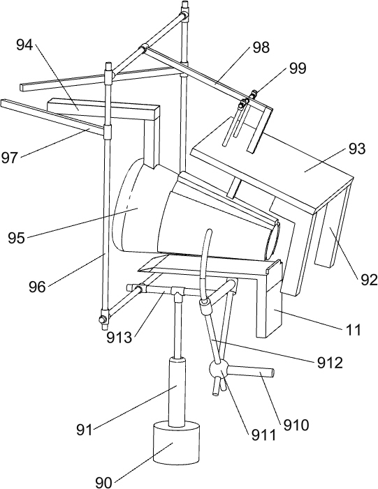
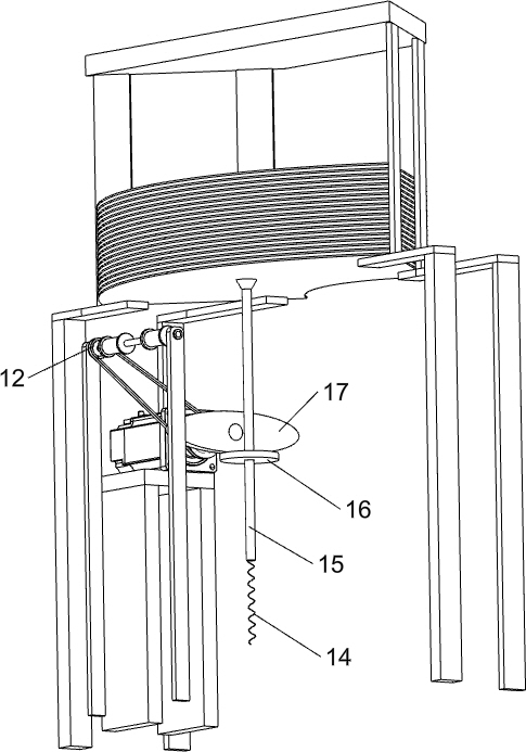

Image

  • Equipment for winding paper cups into cylinders
  • Equipment for winding paper cups into cylinders
  • Equipment for winding paper cups into cylinders

Examples


Embodiment 1

[0021] A device that rolls paper cups into cylinders, such as Figure 1-4 As shown, it includes a bottom plate 1, a support frame 2, a connecting plate 3, a first support member 4, a first servo motor 5, a bearing seat 6, a rotating shaft 7, a conveyor belt 8, a roll forming mechanism 9, a blanking mechanism 10, a placement Platform 11 and pulley assembly 12, two groups of support frames 2 are arranged symmetrically front and back on the left side of the upper part of the bottom plate 1, connecting plates 3 are arranged on the two groups of support frames 2, and the first support member 4 is arranged on the left rear side of the upper part of the bottom plate 1, and the second A first servo motor 5 is arranged on the upper part of a support member 4, and a bearing seat 6 is provided symmetrically front and back in the left side of the upper part of the base plate 1 and in the middle of the upper part of the base plate 1, and a rotating shaft 7 is arranged between the bearing se...

Embodiment 2

[0028] On the basis of Example 1, such as figure 1 and Figure 4 As shown, it also includes a fixed sleeve 13, a return spring 14, a lifting suction cup 15, a fixed disc 16 and a cam 17. The left side of the upper part of the bottom plate 1 is provided with a fixed sleeve 13, and the fixed sleeve 13 is located in front of the first support member 4. side, the fixed sleeve 13 is provided with a return spring 14, and the fixed sleeve 13 is slidingly provided with a lifting suction cup 15, the bottom of the lifting suction cup 15 is connected with the return spring 14, and the upper part of the lifting suction cup 15 is provided with a fixed disc 16, the first servo The output shaft of the motor 5 is provided with a cam 17, and the cam 17 cooperates with the fixed disk 16.

[0029] After the cardboard that needs to be rolled into a tube is placed on the support frame 2, the lifting suction cup 15 will contact the bottom cardboard, and the rotation of the first servo motor 5 will...


PUM


Abstract

The invention relates to equipment for winding into cylinders, in particular to equipment for winding paper cups into cylinders. In order to solve the technical problems, the equipment for winding thepaper cups into the cylinders can sequentially feed paperboards and quickly wind the paperboards into cylinders. The equipment for winding the paper cups into the cylinders comprises one bottom plate, two groups of support frames symmetrically arranged on the left side of the upper part of the bottom plate in a front-back mode, a connecting plate, and a first supporting piece, wherein the connecting plate is arranged on the two groups of support frames; and the first supporting piece is arranged on the left rear side of the upper part of the bottom plate. According to the equipment, the effects that the paperboards can be sequentially fed and can be rapidly wound into the cylinders are achieved, a second lifting rod moves up and down to drive clamping supports on the front side and the rear side to rotate, so that the clamping supports can drive the paperboards to wrap a fixed round table, and the paperboards can be rapidly wound into the cylinders.

Description

technical field [0001] The invention relates to a device for rolling a paper cup into a tube, in particular to a device for rolling a paper cup into a tube. Background technique [0002] A paper cup is a kind of paper container made by mechanically processing and bonding base paper made of chemical wood pulp, with a cup-shaped appearance. Waxed paper cups for frozen food, can hold ice cream, jam and butter, etc. Paper cups for hot drinks are coated with plastic, resistant to temperatures above 90°C, and can even be filled with water. Paper cups are safe and hygienic, light and convenient, and can be used in public places, restaurants, restaurants, and are disposable items. [0003] At present, people manually place the unformed cardboard on the mechanical equipment, and then manually move and rotate the mold continuously, so that the mold can roll the unformed cardboard into a cylinder, and then apply glue through the mechanical equipment Fixed, there is a shortcoming tha...

Claims


Application Information

Patent Timeline
Patent Type & Authority Applications(China)
IPC IPC(8): B31B50/07B31B50/04B31B50/74B31B105/00B31B110/10B31B110/20
CPCB31B50/07B31B50/042B31B50/74B31B2105/0022B31B2110/10B31B2110/20
Inventor 梁闰强
Owner 梁闰强
Learn More