Steel box girder hoisting equipment in complex environment

A hoisting equipment and complex environment technology, which is applied in the direction of transportation and packaging, load hanging components, etc., can solve the problems of inability to ensure the precise positioning of steel box girders, serious shaking of steel box girders, and reduced quality of bridge erection, so as to reduce shaking range, improving construction quality, and reducing costs

Active Publication Date: 2022-01-25
CCCC THIRD HIGHWAY ENG
View PDF0 Cites 1 Cited by
  • Summary
  • Abstract
  • Description
  • Claims
  • Application Information

AI Technical Summary

Problems solved by technology

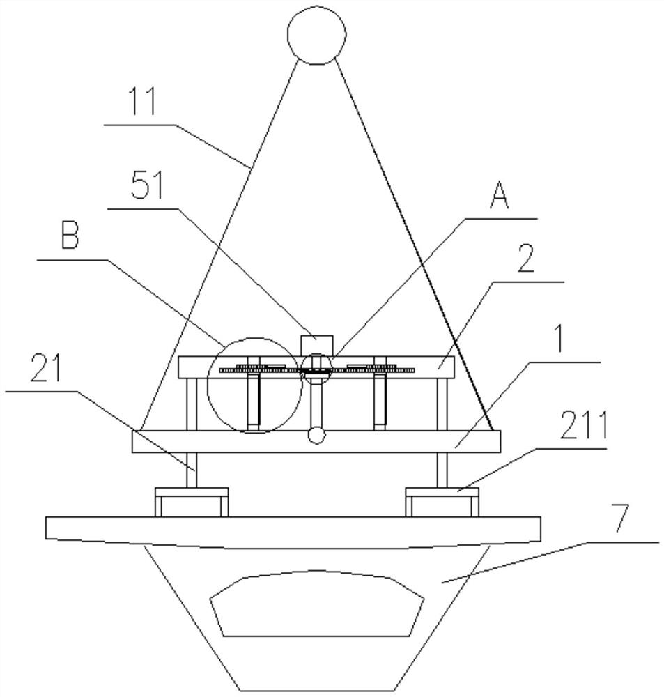
[0002] With the rapid development of the economy of the times, the requirements for the convenience of road traffic are also getting higher and higher. The construction of bridges is undoubtedly one of the most important undertakings to improve the convenience of road traffic. The construction of bridges is usually done through multiple prefabricated The steel box girder is spliced ​​together. During the construction process, the prefabricated steel box girder needs to be hoisted to the construction point by hoisting equipment. During the hoisting operation, the precise positioning of the steel box girder is directly related to the quality of the bridge erection. The existing hoisting equipment will The box girder is directly connected to the hoist through a wire rope. The flexibility of the wire rope causes the steel box girder to shake seriously during hoisting, especially in complex environments such as the sea, which poses a greater safety hazard; other existing hoisting equipment only It is possible to hoist the steel box girder to a location close to the construction, and then adjust the horizontal position and inclination angle of the steel box girder by pulling it manually, which cannot ensure the precise positioning of the steel box girder, which leads to a decrease in the quality of bridge erection

Method used


Image

  • Steel box girder hoisting equipment in complex environment
  • Steel box girder hoisting equipment in complex environment
  • Steel box girder hoisting equipment in complex environment

Examples


Embodiment Construction

[0039] The present invention will be further described below in conjunction with the accompanying drawings and examples to make those skilled in the art can be implemented with reference to the specification.

[0040] It should be understood that, such as "having", "including" and "comprising" as used herein do not exclude presence or addition of one or more other elements or combinations thereof.

[0041] It should be noted that the experimental method described below, as unless otherwise specified, all conventional methods, the reagents and materials, such as non-special instructions, can be obtained from the business pathway.

[0042] In the description of the invention, the term "horizontal", "longitudinal", "upper", "lower", "front", "post", "right", "vertical", "level", " The orientation or location of the indicated by top "," bottom "," inside "," outside ", etc. is based on the orientation or positional relationship shown in the drawings, is only for convenience of descrip...


PUM


Abstract

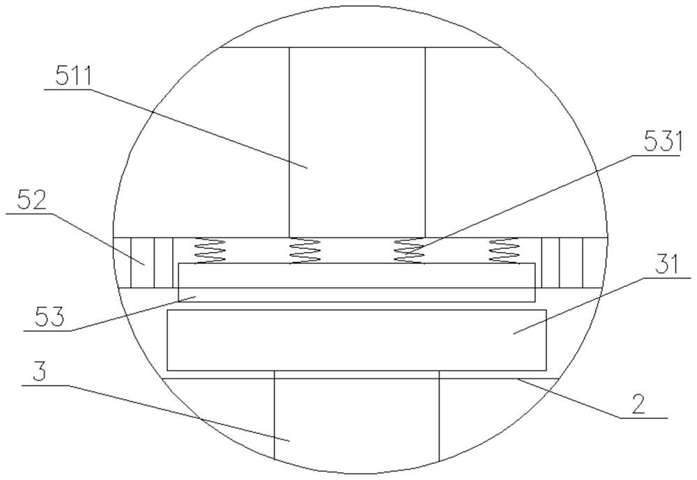
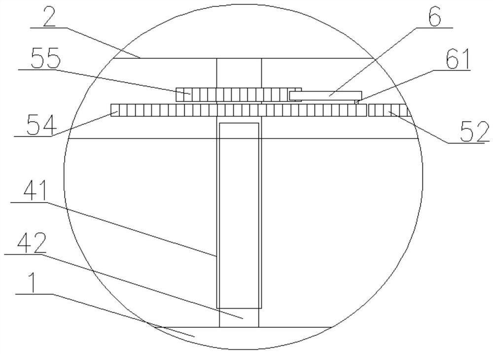
The invention discloses hoisting equipment for a steel box girder in a complicated environment, which comprises: a lower beam body, on which four hoisting points are arranged; an upper beam body, which is located above the lower beam body; The connecting column, the lower end of any connecting column passes through the lower beam body and the bottom of the distribution beam mechanism is connected to the steel box girder to be hoisted; the rotating shaft is located between the upper beam body and the lower beam body, and connects the upper beam body and the lower beam body The middle part of the beam body is rotationally connected; three telescopic rods are located between the upper beam body and the lower beam body, and the two ends of any telescopic rod are respectively connected with the upper beam body and the lower beam body. In the present invention, a transition piece between the upper beam body and the lower beam body is set between the steel wire rope connected with the hoist and the steel box girder to be hoisted, which greatly reduces the shaking range of the steel box girder caused by other external forces (such as wind force) in complex environments , greatly reducing the probability of construction accidents caused by the shaking of the steel box girder during the hoisting process, and improving the completeness of the construction.

Description

Technical field [0001] The present invention relates to the field of bridge construction technology. More specifically, the present invention relates to a complex environmental steel tank beam lifting device. Background technique [0002] With the rapid development of the era, the convenience requirements of road traffic are also increasingly high. The building of bridges is undoubtedly one of the especially important causes of road transportation convenience. The construction of bridges is usually through multiple prefabrication. The steel box beam is spliced, and the prefabricated steel box beam is taken to the construction point during the construction process. During the lifting operation, the precision positioning of the steel box beam is directly related to the quality of the bridge, and the existing hoisting equipment will steel The box girder is directly connected to the lifting machine. The flexibility of the wire rope leads to the slogging of the steel box beams, especi...

Claims


Application Information

Patent Timeline
Patent Type & Authority Patents(China)
IPC IPC(8): B66C1/12B66C13/06
CPCB66C1/12B66C13/06
Inventor 于跟社刘华江何训林隋中州王亚楠
Owner CCCC THIRD HIGHWAY ENG
Why Eureka
Try Eureka