Ultrasonic slitting machine for cloth

An ultrasonic and slitting machine technology, which is applied in the cutting of textile materials, textile and papermaking, fabric surface trimming, etc., can solve problems such as low production efficiency, low production yield, and loose edges

Inactive Publication Date: 2020-10-27
任丘市庆信亨商贸有限公司
View PDF9 Cites 0 Cited by
  • Summary
  • Abstract
  • Description
  • Claims
  • Application Information

AI Technical Summary

Problems solved by technology

[0002] When using the ultrasonic technology to make vermicelli on the cloth, it has the effect of reducing energy loss and improving energy saving. The ultrasonic slitting machine uses the sharp blade of the knife to cut the cloth. When the cloth is driven by the motor and passes through the knife, it is cut by the knife edge. Divide it into multiple strips with smaller width, and then roll the strips into rolls for convenience. However, when the fabric is slitting and

Method used


Image

  • Ultrasonic slitting machine for cloth
  • Ultrasonic slitting machine for cloth
  • Ultrasonic slitting machine for cloth

Examples


Embodiment 1

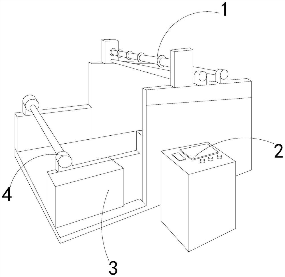
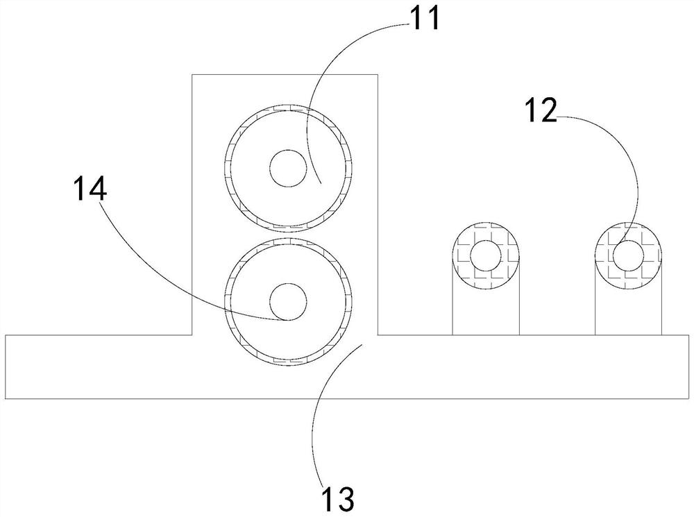
[0023] like Figure 1-Figure 5 Shown:

[0024] The present invention is an ultrasonic cloth slitting machine, its structure includes a rotating mechanism 1, a console 2, a fixed frame 3, a winding rod 4, the winding rod 4 is embedded in the upper end of the fixed frame 3, and the shrinking console 2 is located at On the side of the fixed frame 3, the rotating mechanism 1 is embedded in the upper right side of the fixed frame 3, and the winding rod 4 is parallel to the rotating mechanism 1, and the rotating mechanism 1 is provided with a cutting mechanism 11, a transmission rod 12, a fixed Plate 13, compression mechanism 14, described cutting mechanism 11 fits on the upper end of transmission rod 12, and described compression mechanism 14 is fixed on the inside of fixing plate 13, and described transmission rod 12 is positioned at the left end of cutting mechanism 11, and described fixing plate 13 is positioned at the right side upper end of fixed mount 3, and described transm...

Embodiment 2

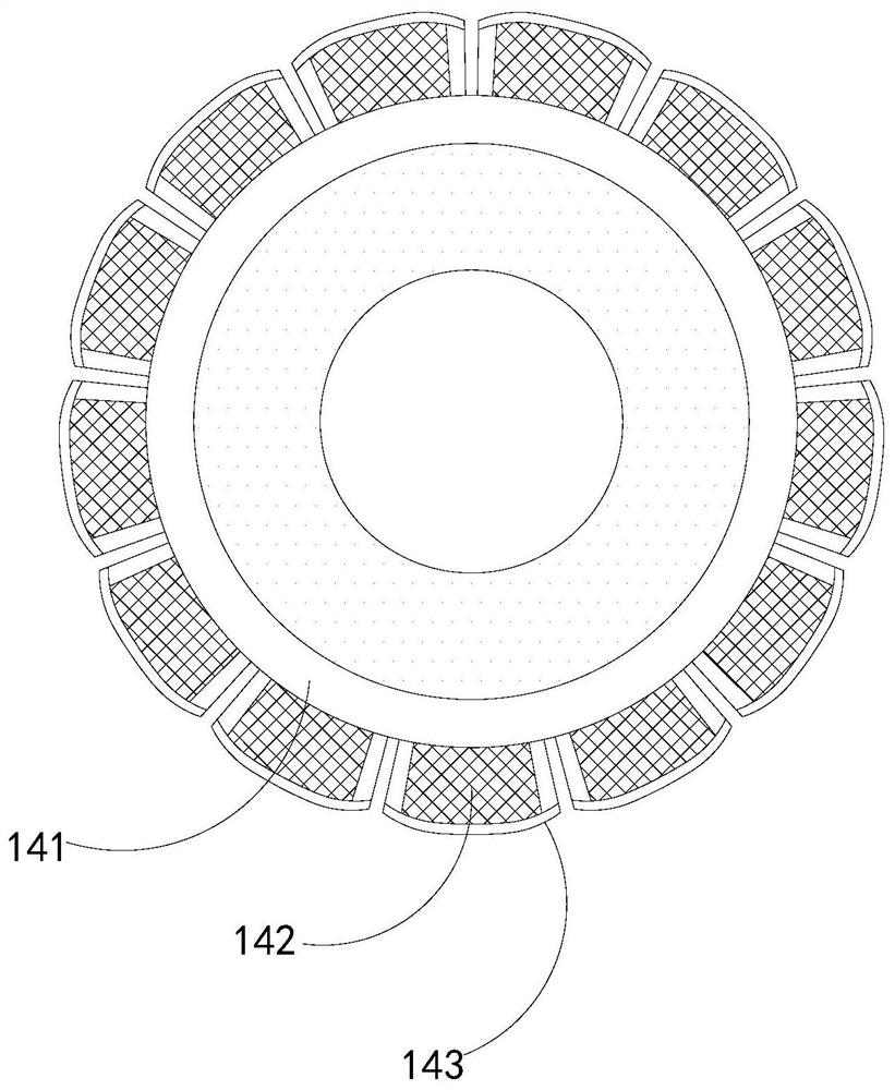
[0031] like Figure 6-Figure 7 Shown:

[0032] Wherein, the cutting mechanism 11 is provided with a rotating shaft 111, a cutting disc 112, an extruding mechanism 113, and a cutting blade 114. , the cutting blade 114 is fixed inside the rotating shaft 111, the pressing mechanism 113 is attached to the upper end of the compression mechanism 14, the cutting blade 114 is located in the middle of the cutting disc 112, and is located on the same vertical line as the compression mechanism 14 On the top, fix the cloth while cutting to prevent the flatness of the cloth from affecting the cutting.

[0033]Wherein, the extruding mechanism 113 is provided with a spring rod a1, a fixed ring a2, a sponge ring a3, a connecting shaft a4, and a sliding ball a5, the spring rod a1 is embedded on the outside of the fixed ring a2, and the sponge ring a3 is attached Closed on the outside of the fixed ring a2, the sliding ball a5 is installed inside the connecting shaft a4, the spring rod a1 is e...


PUM


Abstract

The invention discloses an ultrasonic slitting machine for cloth. The structure of the ultrasonic slitting machine comprises a rotating mechanism, a control console, a fixing frame and a winding rod,wherein the rotating mechanism is provided with a cutting mechanism, transmission rods, a fixing plate and a compression mechanism. Cloth acts on bent plates to compress the bent plates, then compression rods extrude a balance rod, then a spring acts on a stress block, thus air in a sealing groove is discharged through the stress block and acts to a bent groove, fine scraps are blown to flow out from two sides, thus the fine scraps are prevented from being adhered to the slit cloth, the phenomenon that the quality of the slit cloth is poor is further avoided, the influences of the fine scrapson the cut cloth are reduced, in addition, each sliding ball is of a shaft-shaped structure, a triangular structure is distributed on the outer side of each sliding ball, then the grabbing force on the cloth is enhanced, the cloth is prevented from sliding, so that the cloth is smooth, the phenomenon of irregular slitting is avoided, the reduction of tensile strength of cloth strips is prevented,the probability of edge scattering is reduced, and the quality of the cloth is prevented from being affected.

Description

technical field [0001] The invention relates to the field of slitting machines, in particular to an ultrasonic cloth slitting machine. Background technique [0002] When using the ultrasonic technology to make vermicelli on the cloth, it has the effect of reducing energy loss and improving energy saving. The ultrasonic slitting machine uses the sharp blade of the knife to cut the cloth. When the cloth is driven by the motor and passes through the knife, it is cut by the knife edge. Divide it into multiple strips with smaller width, and then roll the strips into rolls for convenience. However, when the fabric is slitting and its edges are relatively soft, it is prone to irregular cutting, resulting in the strip’s tensile strength. Falling, even the problem of loose edges will appear, which will seriously affect the quality of the fabric, and cloth scraps or dust will be generated during cutting. These cloth scraps or dust are easy to adhere to the cut fabric, which will lead ...

Claims


Application Information

Patent Timeline
IPC IPC(8): D06H7/22D06H7/04D06C25/00B26D7/18
CPCB26D7/1854D06C25/00D06H7/04D06H7/223
Inventor 余振露
Owner 任丘市庆信亨商贸有限公司
Why Eureka
Try Eureka