an assembled wall

A prefabricated, wall technology, applied in the direction of walls, buildings, building components, etc., can solve the problems of the formwork positioning of the inner wall, the thickness and dimension deviation of the inner wall, etc., and achieve the goal of ensuring consistency, good thickness and size, and avoiding changes Effect

Active Publication Date: 2022-03-22
周兆弟
View PDF6 Cites 0 Cited by
  • Summary
  • Abstract
  • Description
  • Claims
  • Application Information

AI Technical Summary

Problems solved by technology

[0005] However, the positioning piece can only locate the position of the reinforcement structure, but not the formwork of the inner wall. During pouring, the formwork is deformed under the push of the cylinder, which will cause deviations in the thickness of the inner wall

Method used


Image

  • an assembled wall
  • an assembled wall
  • an assembled wall

Examples


Embodiment 1

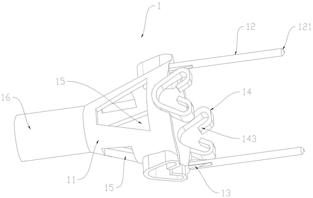
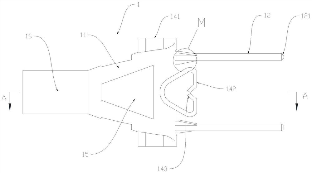
[0033] A prefabricated wall, such as Figure 1 to Figure 10 As shown, it includes an outer wall 2 and an inner wall 3 located inside the outer wall 2. The inner wall 3 is provided with a steel bar structure 10 and a connecting device 1 connected to the steel bar structure 10. The connecting device 1 is used to limit the pouring of the inner wall 3. Thickness, the connecting device 1 includes a connecting buckle 11 and a positioning rod 12, one end of the connecting buckle 11 is connected with the outer wall 2 through the first connecting part 4, the steel bar structure 10 is penetrated in the connecting buckle 11, and the shape of the connecting buckle 11 is a hollow circular platform, A lightening hole 15 for reducing the weight of the connecting buckle 11 is opened on the outer wall of the connecting buckle 11 . The connection buckle 11 is set as a hollow round platform and the weight reduction hole 15 is opened on the connection buckle 11 to reduce the weight of the connect...

Embodiment 2

[0036] A prefabricated wall, such as Figure 1 to Figure 10 As shown, on the basis of Embodiment 1, the connecting buckle 11 is provided with a second connecting portion 16 adapted to the first connecting portion 4 , and the first connecting portion 4 is screwed to the second connecting portion 16 . During construction, the first connecting part 4 is first poured in the outer wall 2, and then the second connecting part 16 is screwed on the first connecting part 4, and then the construction of the inner wall 3 is carried out, which simplifies the connection structure and the operation of construction , the second connecting part 16 is a threaded sleeve provided with an internal thread, the first connecting part 4 is a screw rod provided with an external thread at one end, and the threaded sleeve is screwed on the screw rod. The installation of the connecting device 1 and the screw rod is convenient.

[0037] Of course, in other embodiments, the second connecting part 16 may be...

Embodiment 3

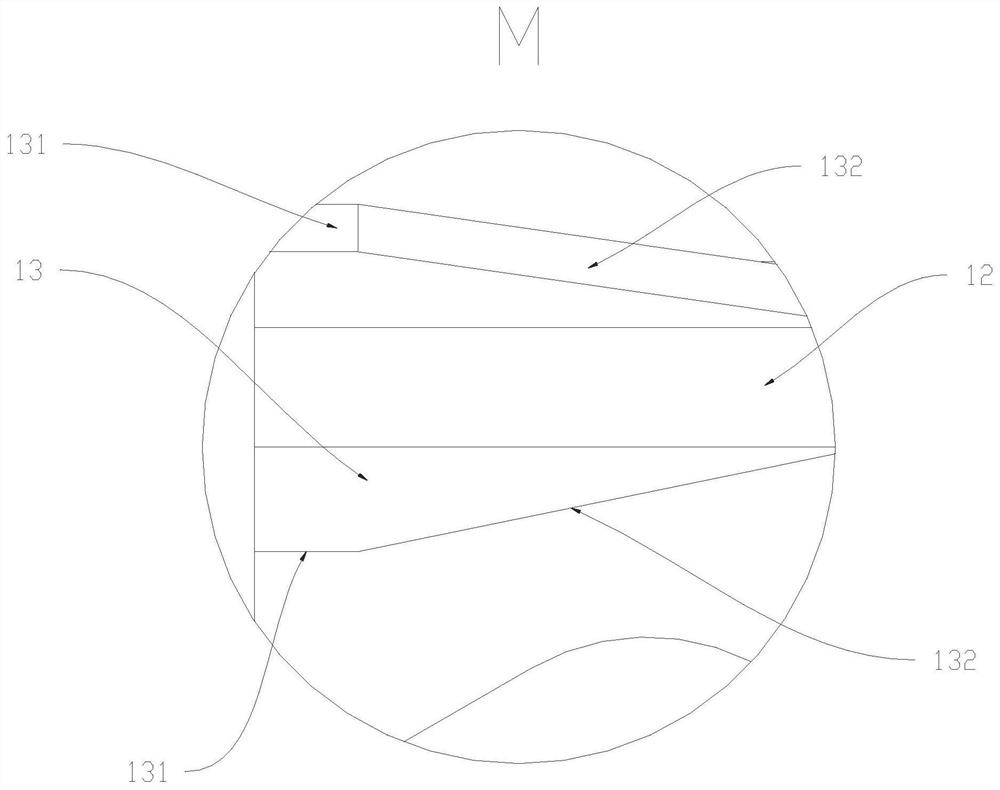
[0042] A prefabricated wall, such as Figure 1 to Figure 10 As shown, on the basis of Embodiment 2, the joint between the positioning rod 12 and the connecting buckle 11 is provided with a supporting block 13 connected to the connecting buckle 11, the supporting block 13 is connected with the outer wall of the positioning rod 12, and the supporting block 13 is axially uniform. Arranged on the positioning rod 12. The support block 13 and the positioning rod 12 are integrally formed, and the shear force of the positioning rod 12 in the vertical direction is enhanced through the support block 13, so as to prevent the positioning rod 12 from being bent by the extrusion of the inner wall formwork, and at the same time strengthen the right end of the positioning rod 12 and the connection The connection strength of the buckle 11, thereby enhancing the overall strength of the positioning rod 12 in the construction process, the inner end surface of the support block 13 is attached to t...


PUM


Abstract

The invention relates to the technical field of building assembly, and discloses a prefabricated wall, comprising an outer wall (2) and an inner wall (3) located inside the outer wall (2), the inner wall (3) being provided with a steel bar structure ( 10) and the connection device (1) connected with the steel structure (10), the connection device (1) is used to limit the thickness of the inner wall (3) pouring, the connection device (1) includes a connection buckle (11) and a positioning rod (12 ), one end of the connecting buckle (11) is connected with the inner wall of the outer wall (2), the steel bar structure (10) is pierced through the connecting buckle (11), and the other end of the connecting buckle (11) is connected with the positioning rod (12), and the positioning Bar (12) is located at the side away from outer wall (2), and the end face of positioning bar (12) away from outer wall is flush with the inner wall of inner wall (3). In the present invention, the ends of a plurality of positioning rods are used to resist the inner wall formwork, so as to avoid the change of the thickness of the inner wall under the push of the cylinder, ensure the consistency of the dimensions of the inner wall during pouring, and better control the thickness of the wall.

Description

technical field [0001] The invention relates to the technical field of building assembly, in particular to an assembled wall. Background technique [0002] There are two types of prefabricated walls, one includes exterior walls and interior walls, and the other includes exterior walls, thermal insulation walls, and interior walls. Both types of prefabricated walls are molded in one mold. Normally, the mold forms the outer wall first, then puts the insulation wall into the mold (if there is no insulation wall, ignore this step), and finally, molds the inner wall. [0003] The pumping mechanism realizes the outer and inner walls of the mold by pumping the concrete into the mould. During the pumping process, the cavity of the mold has a tendency to expand outward under the extrusion of concrete. In order to avoid the deformation of the cavity of the mold during the pumping process, a thrust is usually applied to the template of the mold (for example: providing thrust for the ...

Claims


Application Information

Patent Timeline
Patent Type & Authority Patents(China)
IPC IPC(8): E04B2/00
CPCE04B2/00
Inventor 周兆弟
Owner 周兆弟
Why Eureka
Try Eureka